Finite State Machines (FSMs)
2024.06.22 : I’m Kevin Hubbard, Electrical Engineer. For 30+ years now companies have asked me to design digital logic circuits for them. Which I have, and get this – they even pay me for it. Don’t tell my boss, but I would absolutely do it for free. I started doing digital design in the early 1980’s as a kid. I got hooked designing small interface logic circuits for my 6502 and Z80 8bit computers of the era.
40+ years later, I’m still loving the challenge of digital logic design. It’s a lot like LEGO building, but getting to push electrons around the way you want instead of little plastic cars with rubber wheels. It’s been an amazing journey that I hope others may decide to pursue. I’m giving back now in writing this “Getting started with FPGAs” series which starts here.
In Part-7 I explained RTL hierarchy and the importance of splitting designs into smaller modules. In Part-8 I will explain finite state machines, often referred to as FSMs. Let’s begin.
If you’ve been reading along since the beginning of this tutorial, you’ll know that a persistent gripe of mine is when people think FPGAs are somehow like microcontrollers. I’m forever explaining that microcontrollers are just mini-computers and they run software. Software which is executed sequentially. FPGA’s aren’t like that at all. They don’t execute code. They connect up gates and those gates all run concurrently. It’s true. You can actually build a microcontroller inside an FPGA but the reverse is never true. Microcontrollers are sequential. One line of assembly code after another.
But here’s the thing – sometimes you need an FPGA to explicitly do something in series. They can do that, but you have to design for it using something called a “finite state machine“. A traffic light is a perfect example of a finite state machine. It has exactly three states of Green ( GO ), Red ( STOP ) and Yellow ( transitioning from GO to STOP ).
A very simple state machine for a stop light might look like this in Verilog :
`timescale 1 ns/ 100 ps
`default_nettype none // Strictly enforce all nets to be declared

module traffic_light
(
  input  wire       clk,
  input  wire       reset,
  input  wire       pulse_5s,
  output wire       light_green,
  output wire       light_yellow,
  output wire       light_red
);// module traffic_light

  reg  [3:0]  tl_fsm_sr = 4'b0001;

always @ ( posedge clk or posedge reset ) begin
  if ( reset == 1 ) begin
    tl_fsm_sr <= 4'b0001;
  end else begin
    if ( pulse_5s == 1 ) begin
      tl_fsm_sr <= {tl_fsm_sr[2:1],(tl_fsm_sr[3]|tl_fsm_sr[0]),1'b0};
    end
  end
end
  assign light_green  = tl_fsm_sr[1];
  assign light_yellow = tl_fsm_sr[2];
  assign light_red    = tl_fsm_sr[3];

endmodule // traffic_light.v
`default_nettype wire // enable Verilog default for 3rd party IP
Under simulation, it looks like this:
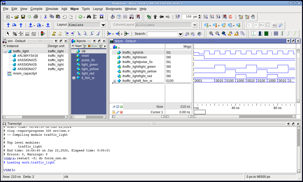
It’s a 4 state one-hot encoded FSM. One-hots are my favorite as they tend to make timing closure with ease. That said, it’s also a bit cryptic to read. For example, this line really needs explaining:
“tl_fsm_sr <= {tl_fsm_sr[2:1],(tl_fsm_sr[3]|tl_fsm_sr[0]),1’b0};”
It’s a four state state machine, State-0 is the reset state. It’s good FSM design practice to always have a reset state and coming out of reset immediately jump to State-1. After that, the FSM just round robin rotates State-1 to State-2 to State-3 back to State-1, etc. Simple FSMs are reliable FSMs and easy to simulate all possible states.
I will frequently write simple state machines just like this. They are compact and reliable. This method tends to fall apart going beyond 1/2 a dozen states though. Thankfully, RTLs like Verilog and VHDL support descriptive state machine definitions. The same state machine in Verilog but using binary encoding looks like this:
`timescale 1 ns/ 100 ps
`default_nettype none // Strictly enforce all nets to be declared

module traffic_light
(
  input  wire       clk,
  input  wire       reset,
  input  wire       pulse_5s,
  output reg        light_green,
  output reg        light_yellow,
  output reg        light_red
);// module traffic_light

  localparam[1:0]
    FSM_ST_ZERO  = 2'h0,
    FSM_ST_ONE   = 2'h1,
    FSM_ST_TWO   = 2'h2,
    FSM_ST_THREE = 2'h3;
  reg [1:0] tl_fsm_st = 2'd0;

always @ ( posedge clk or posedge reset ) begin
  if ( reset == 1 ) begin
    tl_fsm_st    <= FSM_ST_ZERO;
    light_green  <= 0;
    light_yellow <= 0;
    light_red    <= 0;
  end else if ( pulse_5s == 1 ) begin
    light_green  <= 0;
    light_yellow <= 0;
    light_red    <= 0;
    case( tl_fsm_st )
      FSM_ST_ZERO  : begin
          tl_fsm_st    <= FSM_ST_ONE;
        end
      FSM_ST_ONE   : begin
          tl_fsm_st    <= FSM_ST_TWO;
          light_green  <= 1;
        end
      FSM_ST_TWO   : begin
          tl_fsm_st    <= FSM_ST_THREE;
          light_yellow <= 1;
        end
      FSM_ST_THREE : begin
          tl_fsm_st    <= FSM_ST_ONE;
          light_red    <= 1;
        end
      default : begin
          tl_fsm_st <= FSM_ST_ZERO;
        end
    endcase // tl_fsm_st
  end
end

endmodule // traffic_light.v
`default_nettype wire // enable Verilog default for 3rd party IP
Easier to read, right? It’s also twice the size in terms of line numbers. In terms of logic, it’s about a wash. The 1st implementation was one-hot and required 4 flip-flops and an OR gate. The 2nd implementation was binary-encoded with just 2 flip-flops and some LUTs for a counter-ish type implementation. Which is better? Every design is different. Here’s the identical FSM but in VHDL for completeness :
LIBRARY ieee ;
USE ieee.std_logic_1164.all;
USE ieee.std_logic_arith.all;
USE ieee.std_logic_unsigned.all;
LIBRARY std ;

entity traffic_light is
port
(
  clk          : in  std_logic;
  reset        : in  std_logic;
  pulse_5s     : in  std_logic;
  light_green  : out std_logic;
  light_yellow : out std_logic;
  light_red    : out std_logic
);
end traffic_light;

architecture rtl of traffic_light is

  type tl_state_type is
  (
   FSM_ST_ZERO,
   FSM_ST_ONE,
   FSM_ST_TWO,
   FSM_ST_THREE
  );
  signal tl_fsm_st : tl_state_type ;

begin

process ( clk, reset )
begin
  if ( reset = '1' ) then
    tl_fsm_st    <= FSM_ST_ZERO;
    light_green  <= '0';
    light_yellow <= '0';
    light_red    <= '0';
  elsif ( clk'event and clk = '1' ) then
    if ( pulse_5s = '1' ) then
      light_green  <= '0';
      light_yellow <= '0';
      light_red    <= '0';
      case tl_fsm_st is
        when FSM_ST_ZERO =>
          tl_fsm_st    <= FSM_ST_ONE;
        when FSM_ST_ONE  =>
          tl_fsm_st    <= FSM_ST_TWO;
          light_green  <= '1';
        when FSM_ST_TWO  =>
          tl_fsm_st    <= FSM_ST_THREE;
          light_yellow <= '1';
        when FSM_ST_THREE  =>
          tl_fsm_st    <= FSM_ST_ONE;
          light_red    <= '1';
        when others =>
          tl_fsm_st    <= FSM_ST_ZERO;
      end case;
    end if;
  end if;
end process;
end rtl;-- traffic_light.vhd
If you compare the VHDL with the Verilog, you’ll notice they are 99% the same. The syntax is just slightly different. I’m completely agnostic anymore. Given the choice, I’ll start a new design in Verilog. Given an existing VHDL legacy design, I’ll continue writing new modules in VHDL. I only get into typing trouble if I’m trying to write both VHDL and Verilog in the same day. Finger muscle memory is like that. Switching back and forth is like switching between a piano and a glockenspiel.
You will notice the case statements in both Verilog and VHDL have a “others” or “default” clause that forces the state machine back to a reset state. It’s VERY important to establish a “safe mode” for binary encoded state machines as all possible states might not be defined, but may indeed happen in circuit due to “Cosmic Ray” or other anomalies ( power supply glitch, over temperature failed timing, etc ).
What this means in real logic implementation is that a binary encoded FSM RTL design might have only 5 defined states, but is still implemented in FPGA fabric using a 3-bit counter with 8 possible states. By following this simple “others/default” practice, states 6,7 and 8 become defined in hardware. Their definition may someday prevent your state machine from getting “stuck” in an undefined state and locking up the entire design.
I will close with a full-up FSM for a traffic light. I’ve added a timer so that the green, yellow, red cycles will last 10s, 5s and 15s each. In addition, I added two inputs for an emergency vehicle and power outage.
`timescale 1 ns/ 100 ps
`default_nettype none // Strictly enforce all nets to be declared

module traffic_light
(
  input  wire       clk,
  input  wire       reset,
  input  wire       pulse_1s,
  input  wire       nmi_emergency_vehicle,
  input  wire       nmi_power_outage,
  output reg        light_green,
  output reg        light_yellow,
  output reg        light_red
);// module traffic_light

  localparam[1:0]
    FSM_ST_RESET   = 2'h0,
    FSM_ST_GREEN   = 2'h1,
    FSM_ST_YELLOW  = 2'h2,
    FSM_ST_RED     = 2'h3;
  reg [1:0] tl_fsm_st = 2'd0;
  reg [3:0] timer_cnt = 4'd0;
  reg       flash_togl = 0;

always @ ( posedge clk or posedge reset ) begin
  if ( reset == 1 ) begin
    tl_fsm_st    <= FSM_ST_RESET;
    light_green  <= 0;
    light_yellow <= 0;
    light_red    <= 0;
    timer_cnt    <= 4'd0;
  end else if ( pulse_1s == 1 ) begin
    flash_togl   <= ~ flash_togl;
    light_green  <= 0;
    light_yellow <= 0;
    light_red    <= 0;
    if ( timer_cnt != 4'd0 ) begin
      timer_cnt <= timer_cnt - 1;
    end
    case( tl_fsm_st )
      FSM_ST_RESET : begin
          tl_fsm_st    <= FSM_ST_GREEN;
          timer_cnt    <= 4'd10;
        end
      FSM_ST_GREEN : begin
          light_green  <= 1;
          if ( timer_cnt == 4'd0 ) begin
            tl_fsm_st    <= FSM_ST_YELLOW;
            timer_cnt    <= 4'd5;
          end
          if ( nmi_emergency_vehicle == 1 ) begin
            tl_fsm_st    <= FSM_ST_YELLOW;
            timer_cnt    <= 4'd5;
          end
        end
      FSM_ST_YELLOW : begin
          light_yellow <= 1;
          if ( timer_cnt == 4'd0 ) begin
            tl_fsm_st    <= FSM_ST_RED;
            timer_cnt    <= 4'd15;
          end
        end
      FSM_ST_RED : begin
          if ( nmi_power_outage == 1 ) begin
            light_red    <= flash_togl;
          end else begin
            light_red    <= 1;
          end
          if ( timer_cnt == 4'd0 &
               nmi_emergency_vehicle == 0 &
               nmi_power_outage == 0        ) begin
            tl_fsm_st    <= FSM_ST_GREEN;
            timer_cnt    <= 4'd10;
          end
        end
      default : begin
          tl_fsm_st <= FSM_ST_RESET;
        end
    endcase // tl_fsm_st
  end
end

endmodule // traffic_light.v
`default_nettype wire // enable Verilog default for 3rd party IP
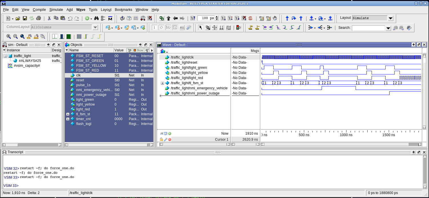
The simulation below walks through two normal light cycles. The 3rd cycle is interrupted by an emergency vehicle, making the light rapidly transition from green to yellow and then stay at red until the emergency vehicle has cleared the intersection. It ends with a power outage, which causes the red light to flash every second – forcing a four-way stop behavior for drivers.
This ends Part-8 of the series. It was a lot of fun to create. I remember being IDK, maybe 10 years old or so in 1980 and having Green, Yellow and Red LEDs from my local RadioShack hooked up to a 74374 octal-latch on a breadboard connected to my TRS-80 Model-1 8bit Z-80 and writing a BASIC program with OUT statements that turned on the LEDs in sequence as if they were a traffic light. It was an exciting accomplishment for a little kid learning about electronics. I’ve come full circle today revisiting the humble traffic light state machine – but now purely in hardware. Thanks for reading. See you next time for Part-9, whatever it may be.
EOF

[…] BML FPGA Design Tutorial Part-8ofN […]
LikeLike
[…] BML FPGA Design Tutorial Part-8ofN […]
LikeLike
Thanks for writing this series, it’s very informative and reads nicely.
I eventually managed to work out what all the verilog syntax was doing!
I’ve been wanting to try FPGA development for a while now, but unfortunately haven’t thought of any project that needs it!
LikeLike