2024.04.21 : Intel currently ( 2024 ) makes the ModelSim Questa “Intel® FPGA Starter Edition SW-QUESTA” free to use – which is pretty fantastic. Will this fantastic EDA tool deal continue as Altera gets spun-off as a standalone company from Intel? I have no idea – but I do think it’s a great time to install “SW-QUESTA” on my home Linux and Windows machines. I like to write VHDL and Verilog RTL just for fun – so here’s a quick tutorial on how you can too!
[ Downloading the Software for Linux / Windows from Intel ] For Linux, “Razer6” has a great writeup here on GitHub for an Ubuntu installation. The only complication was the need to install some old 32bit packages using: sudo dpkg –add-architecture i386 sudo apt-get update sudo apt-get install libc6:i386 libncurses5:i386 libstdc++6:i386 lib32ncurses6 libxft2 libxft2:i386 libxext6 libxext6:i386
Then run the installer and modify your .bashrc file with: export PATH=$PATH:/opt/modelsim_ase/bin
I actually have two Linux workstations at Black Mesa Labs, “GLaDOS” and “Lambda“. “GLaDOS” is my primary workstation and runs FC19 ( Fedora Core 19 aka Schrödinger’s Cat ) an equivalent to RHEL7. It’s REALLY old ( 2013 ) – but I have Xilinx WebPack ( also free ) installed and running on it for my many BML Spartan3 and Spartan6 FPGA designs, so I keep it around. It’s a great SOP – take old unwanted laptops, slap in a new SSD for $30 or so and install the latest Linux and run it headless in the background with just power and ethernet connection.
“Lambda” is a modern Ubuntu 22.04.3 LTS 64bit installed on a gaming laptop gifted to me recently ( ASUSTek G551JM, Intel Core i&-4710HQ 2.5 GHz x 8, 16 GB DRAM and a 256 GB SSD ). I use “Lambda” when I need to install modern software packages, most recently the “cc65” C compiler for making Apple ][+ programs. I just “ssh -X” into Lambda from GLaDOS and everything – including GUI apps just work. I should mention that even though GLaDOS is my “desktop” Linux workstation – it’s actually headless. I use a NoMachine client from a generic MS-Windows desktop – my actual desktop computer with screens, a keyboard, mouse, speakers, etc.
Anyways – the Ubuntu install on “Lambda” went just fine – although it took at least half an hour. The installer launched on “GLaDOS” no problem, but complained about lack of disk space, requiring 5GB with only 4GB available. It’s a 64 GB SSD from 2013 – so I’m not too surprised or disappointed. “GLaDOS” will need to sunset someday anyways. Computer operating systems age about like dogs do. Way too fast.
The MS-Windows install was super simple, just downloaded the EXE from the Intel website here. Complications only started with licensing.
[ Licensing ] For whatever reason – the Linux version doesn’t require a license file and it just runs. How great is that??The MS-Windows version though – it requires a LICENSE.DAT file that is node locked to your PC’s Ethernet MAC address. It was quite the process getting this (free) file. I almost gave up in tears. Story continues…
Step-1 : Enroll for Intel FPGA Self Service Licensing Center ( SSLC ) at this link . This was fairly straightforward ( at 1st ) entering my email address and creating a password. Later on I discovered that thanks to browser cookies, you can only do this once. To create an account with my alternate email, I had to use a different (Edge) browser. Why two accounts? I’d like to install this on my work laptop for those times I’m away from the license server ( think on planes, trains and automobiles ).
Step-2 : Login to eventually request a license from here. Things got really strange though. I got stuck in a Microsoft / Intel Azure loop of hell. To request the Intel license, I had to login not using my new Intel account ( my email + password ) but using my existing home MS-Azure account ( email + password ). It wouldn’t let me though. It said I had to configure MFA authentication. The thing is, I only have one cell phone number and it’s tied to my other (not home) MS-Azure account. Now even though I went through Microsoft Azure and configured a 2nd email as my MFA – Intel Azure wouldn’t accept it. It demanded either a cellphone number or an authenticator app. I don’t quite understand Azure.
So I punted. Rather than getting a 2nd cellphone, I researched authenticator apps and downloaded and installed “Google Authenticator” on my existing cell phone and gave that to Intel’s Azure and it got me in ( finally ) to request a license file. TBH – I almost gave up. Now I’m left wondering when I will need to use “Google Authenticator”. When I login to MS Azure here – it still has my backup 2nd email as my MFA – with no mention of “Google Authenticator”. So apparently I only need this for my new Intel account. I really don’t understand Azure.
Step-3 : Collect your MAC ID ( from a DOS box type “ipconfig /ALL” – its the 12 digit hex number for your Ethernet adapter ). Submit and receive a LICENSE.DAT file via email. Now under [ This PC ],[ Properties ], [ Advanced System Settings ],[ Environment Variables ] create a new variable “LM_LICENSE_FILE” and point it to LICENSE.DAT. Again – this step is not necessary for Linux. Strange.
In summary, if you don’t have an Azure account or you do but not willing to share an MFA with Intel – you’re not getting a license file for running ModelSim Questa on MS-Windows. Sorry Charlie.
[ Intel / Altera Customized ] So what is Intel/Altera about this version of ModelSim Questa? It comes pre-bundled with Altera FPGA gate primitive libraries installed and ready to go. It’s a hassle to install these manually, so this version does all the work for you ( which is also why the install is 5 GB ).
[ Compiling your design ] From the command line ( DOS or Linux shell ) type “vlog foo.v” or “vcom foo.vhd” where foo.* is your Verilog or VHDL RTL file. Note that the compile commands are different. Why exactly? Long ago legacy license reasons I suspect. With large designs with multiple levels of hierarchy, I typically make a “vcom.sh” script to compile everything. Much like nuking LV-426 from orbit – recompiling every single file of a large design is the only way to be sure everything is up to date in the “./work” library.
[ Simulating your design ] From your OS’s command line ( DOS or Linux shell ) type “vsim foo”
[ Observing your signals ] In the “Objects” window, right-click on signal names and select “Add Wave”. Alternatively, from the “Transcript” command line type “add wave *” to view all signals at this hierarchy level. “*” can be replaced with a specific signal name. All of these commands may be scripted up in a “do file” too of course.
[ Simulate your design ]
I typically generate “do files” as stimulus that look like this: force reset 1 force enable 1 force clk 0 5 ns, 1 10 ns -repeat 10 ns run 10 ns force reset 0 run 100 ns
and then from the “Transcript” command line type this: restart -f; do foo.do Now’s a great time to ask – “Why use ‘do files’ instead of writing a test bench?”. Great question. Test benches – although useful – can also be very deceiving. A person may write a test bench and decide – “well if it passes the test bench then my circuit is golden.” – but that’s absolute bullshit. Does the test bench launch stimulus signals at clock-0 and read the results? Or does it launch at clock +1, +2, +3, +4 etc relative to other stimulus? I’m all for exhaustive test benches with random number generators. I’m all against test benches that test exactly one single scenario out of many possible. “Do Files” allow for rapidly iterating and testing multiple scenarios. I’m all in for that. That’s golden.
[ In Closing ] All in all this ModelSim Questa “Intel® FPGA Starter Edition SW-QUESTA” install went very well. If it wasn’t for the MS-Windows install requiring the license file from Intel Azure hell – it would have been quite simple. One issue I did have ( both on Windows and Linux ) was the Waveform window only displaying “-No Data-” after a simulation, with no sim results displayed. I tracked this down to a very strange incompatibility between Modelsim and my Synology NAS ( Network ) drive regarding the simulation *.WLF file. I suspect Modelsim does an write-append operation while also reading the same file handle and Synology doesn’t support this and Modelsim appears to read 0 content file. Thankfully I figured out a workaround. I can use the “-wlf” flag for vsim to store the *.WLF file locally. For example: vsim foo -wlf ~/vsim.wlf ( Linux ) vsim foo -wlf C:\temp\vsim.wlf ( Windows )
Alternatively, modify the modelsim.ini file to look like this: WLFFilename = /home/khubbard/vsim.wlf
It didn’t like “~/vsim.wlf” for whatever reason. There’s a bunch of WLF flags and there may be one that makes it work just fine writing to Synology NAS. I’ll experiment more in the future.
This “Free” version of Modelsim Questa from Intel/Altera is definitely slower and less capable than the commercially licensed version. Reportedly runs at 40% speed of purchased versions. It’s also less expensive – which is great for hobbyists like myself. That said, I was shocked ( pleasantly surprised ) to see it simulate my mixed Verilog and VHDL design below without issue. Years ago that would suck up two simulation licenses and really steered people away from mixed designs for a poor reason.
Having used ModelSim professionally for 30 some years – I’m very excited to be using it at home now too. It’s a great ( the best IMHO ) RTL simulator and I’m excited that more people will be able to use it going forward. Expect to see more detail in future BML blogs on using ModelSim Questa. For Example, Come back next time and I’ll discuss test benches and VCD file exports and imports from both ModelSim and the BML Sump3 ILA.
2024.04.27 : Update – I got ModelSim running on my 11 year old Fedora Core 19 Linux workstation. Took a lot of Googling and “yum install” trial and errors to get all the libraries needed. yum –enablerepo=fedora clean metadata cd to /etc/yum.repository.d and replace all https with http in files yum update yum yum update yum install libXtst yum install libXext yum install libXrender.x86_64 yum install libXext.i686 yum install libXft.i686 yum install libgcc yum install libgcc.i686 yum install tkimg yum install tkimg.i686
2024.03.11 : SUMP3 is a new generation of the SUMP2 ILA ( Integrated Logic Analyzer ) that was first introduced in 2016 by Black Mesa Labs. The Verilog RTL and Python GUI software for SUMP3 is available on GitHub here.
Like SUMP2, SUMP3 uses real-time hardware RLE ( Run Length Encoding ) compression to potentially store millions of clocked time samples in just a few thousand RAM cells ( mileage may vary ). SUMP2 hardware and software limited capturing only 32 signals simultaneously and the maximum capture time was limited to a few hundred milliseconds. SUMP3 does away with those limits and can capture seconds to minutes worth of activity simultaneously from up to 2^8 x 2^8 x 2^13 signals. SUMP2 was limited in max capture time by a 2^15 watchdog timer that guaranteed valid RLE samples always filled the RAM. SUMP3 removes this limitation and is able to capture a near infinite ( 2^64 clocks ) time of no activity. You read that right – SUMP3 can use a single RAM cell to indicate there was no activity in the last 2^64 clock cycles!
SUMP2 was designed in 2016 for 90 nm FPGAs when RAM in small FPGAs was very limited. An AMD/Xilinx Spartan3 FPGA may have only 20 1Kx36 BRAMs. SUMP2 was designed to use a single BRAM in designs like this for capturing ~1 mS of 32 signals. SUMP2 accomplished what it was originally designed to do, but it was never designed to scale up.
SUMP3 is designed with 2nm FPGAs with abundant RAM in mind. Even today’s 16nm AMD/Xilinx VU9P with 3 chiplets has over 2000 1Kx36 BRAMs, 1000 8Kx36 UltraRAMs and 2 million D flip-flops.
FPGAs are no longer single pieces of silicon. New Stacked Silicon Interconnect (SSI) technology combines multiple FPGA “chiplets” onto a single interposer. Gate and RAM resources grow while inter-chiplet metal routing resources shrink. Timing closure and routing congestion are more critical than a handful of BRAMs.
SUMP2 can only scale beyond 32 signals using muxes. Multiple muxes results in cross chip/chiplet routing congestion. Even with the muxes, old SUMP2 can only ever capture 32 RLE signals at once.
SUMP3 uses distributed localized RLE Pods and Hubs. Localized capture minimizes global routing impacts, improves timing closure and maximizes number of RLE signals captured at once. SUMP3 also adds the ability to capture in multiple ( up to 256 ) clock domains.
SUMP3 may have 1-256 RLE Hubs with each RLE Hub having their own clock domain. A single RLE Hub may interface with 1-256 RLE Pods and a single pod may have between 1 to 8K signals ( 32 nominal ).
Each RLE Pod can be thought of as an original SUMP2 RLE instance. The major difference is that instead of a 32 bit local bus interface requiring 68 wires, a SUMP3 RLE pod requires only a single MISO/MOSI pair that routes up to an RLE Hub. The SUMP3.PY GUI software is then able to individually identify and address up to 2^8 x 2^8 = 65536 instances of RLE Pods.
SUMP3 scales very large and yet can still scale down to being no bigger than SUMP2.
BD_SERVER.PY remains as the low-level software interface bridging the GUI ( SUMP3.PY ) to the 32 bit local bus interface. The SUMP2 example design includes a simple FTDI UART bridge. Other interfaces such as actual PCIe may be designed for specific target needs.
SUMP3 introduces the concept of “View ROMs”. Instead of having to manually create a signal mapping file, net names and FSM state definitions are now stored inside the FPGA itself in a view ROM – making SUMP3 “play-and-play” for configuration.
Want to quickly try SUMP3.py and see what it’s like? Like PZA concept makes that possible. A PZA file is a complete capture database that may be taken offline away from target hardware and viewed. To try the GUI, just download the two files “sump3.py” and “sump3_0016.pza” from my GitHub site here . You’ll need to “pip install pygame-gui” module from the internet. After that, launch, click [Acquisition],[Load_PZA]. After the PZA is loaded, click [Views] and select multiple views ( Pods ) to apply. Then click [Display] and start Zooming, Panning and measuring the captured signals. Enjoy!
2017.12.19 : Black Mesa Labs is presenting an open-source-hardware USB 3.0 to FPGA PMOD interface design. First off, please lower your expectations. USB 3.0 physical layer is capable of 5 Gbps, or 640 MBytes/Sec. This project can’t provide that to your FPGA over 2 PMOD connectors – not even close. It does substantially improve PC to FPGA bandwidth however, 30x for Writes and 100x for Reads compared to a standard FTDI cable based on the FT232 ( ala RS232 like UART interface at 921,600 baud ). A standard FTDI cable is $20 and the FT600 chip is less than $10, so BML deemed it a project worth pursuing.
Measured Data Transfers comparing FT600 to FT232:
USB 3.0 to FT600 at 100 MHz: Writes=1,384 KBytes/Sec, Reads=567 KBytes/Sec
USB 3.0 to HUB to FT600 at 100 MHz: Writes=416 KBytes/Sec, Reads=187 KBytes/Sec
USB 2.0 to FT600 at 100 MHz: Writes=279 KBytes/Sec, Reads=131 KBytes/Sec
USB 2.0 to FT232 1×6 0.100″ at 1 Mbps: Writes=43 KBytes/Sec, Reads=5 KBytes/Sec
Wait, what? Measured in KBytes not MBytes per second? Is BML to blame? Only partly. This BML project utilizes 1/4 of the LVCMOS bandwidth possible of the FT600 to both make the IO fit across PMODs and also work with existing Mesa Bus Protocol IP. The FT600 has 16 data pins capable of 200 MBytes/Sec but 1/2 the data pins are deliberately tossed to fit within 2 PMODs ( 3 PMODs wouldn’t be practical ). Existing Mesa Bus Protocol IP is used – which transfers ASCII nibbles (0-9,A-F) instead of binary, so the maximum logical throughput is reduced another 2x to 50 MBytes/Sec. Observed transfers are just over 1 MByte/Sec. This means if all 16 pins were used and a binary protocol transfer instead of ASCII, rate would be about 5MBytes/Sec – still away off from 200 MB/s . So what is going on? This is a perfect application for the SUMP2 Logic Analyzer from BML. Instead of wiring up the iceStick, SUMP2 was instantiated directly in the FPGA along with the FT600 interface ( this is really what SUMP2 is designed for, a free open-source replacement for Xilinx ChipScope and Altera SignalTap. SUMP2 supports capturing 32 compressed events and up to 16 non-compressed DWORDs into on-chip FPGA block RAM ). Below is a PNG screen dump of SUMP2 capturing the FT600 FIFO status flags (RXF,TXE) and the FPGAs control signals ( RD,WR ). What is immediately apparent is that the majority of the time ( ~154uS out of ~160uS ) the FT600 doesn’t have any data for the FPGA. RXF is sitting low even though Python is trying to send data as fast as possible.
Within a 10 ns clock cycle of RXF asserting, the FPGA asserts RD and converts the Mesa Bus Packet into a local bus burst ( with about 350ns of pipeline latency ). The observed distance between the 32bit lb_wr pulses is precisely 8 clocks, the fastest possible ( DWORD = 4 Bytes x 2 ASCII Bytes per Binary Byte = 8 clocks ). Clearly both the FT600 and the FPGA design are working as fast as possible with what is coming down the USB 3 pipe.
So, the truth is that the majority of the time ( 154/160us = 96% ) the PMOD interface is sitting idle even though Python is trying to write and read from the FT600 as fast as it can. Clearly the USB 3.0 pipe is not full. Who is to blame? Is it Python? Windows? Intel Chipset? Don’t know. Would it be faster on Linux? Hopefully. Would compiled C be faster than Python? Probably. Would we ever achieve 50 MBytes/Sec? Probably not. FTDI Application Note AN_386 goes into some detail, there is a lot of software between the user software and when the electrons finally hit the USB 3.0 cable.
Is just over 1MBytes/Sec a disappointment? Yes. A show stopper? No. Using the FT600 is still the fastest way (BML is aware) of inexpensively getting data from a PC into any FPGA without instantiating a PCI Express IP core and building a PCI Expresss plug in card. 30x and 100x improvements on Writes and Reads is substantial.
2017.12.20 – Update, an acquaintance on Twitter has reported using an FT600 with a proper C client over an FMC connector (all 16 pins, 100 MHz, binary transfers ) of 185 MB/s ( out of 200 MB/s total ). That is excellent news and proof that Python is most likely the bottleneck. Based on his results, the BML dual-PMOD board should be capable of 1/4 that ( 8bit, ASCII ) or 46 MB/s. Github link to C source is here.
2017.12.21 – Update – another acquaintance on Twitter has reported achieving 240 MB/s using FT601 ( 32bit ) and C on Linux. His USB interface software is on Github here.
Now that performance explained – About the design, let’s begin:
[ Software Setup ]
Step-1) Download and install FTD3XX Device Driver from FTDIchip.com . For example, for Windows, download and run FTD3XXDriver_WHQLCertified_v1.2.0.6_Installer.exe
Step-2) Download and install Python module for D3XX from FTDIchip.com. For example, unzip D3XXPython_Release1.0.zip, “%cd D3XXPython_Release1.0” and then “%python setup.py install”
Step-3) Create a directory for your script and copy FTD3XX.dll and FTD3XX.lib from unzipped D3XXPython_Release1.0 folder.
[ Hardware Setup ]
Board design. The board is a 2-layer PCB that is available either via Gerber download or direct purchase from OSH-Park here ($10 for Qty-3). The board consists of the FT600 chip from FTDI, 3 LDO regulators, a 30 MHz crystal and a bunch of 0603 and 0805 passives ( 10uF, 0.1uF, 18pF, 10K, 1.6K, 33 ohm, Ferrite Bead ).
FPGA Hardware setup is a bunch of Verilog IP. I/O timing over the PMODs was tight, so a PLL is used to remove clock tree insertion delay on the 66/100 MHz clock provided by the FT600. Xilinx Spartan3 LVCMOS 3.3V 8mA Fast IO buffers were required to run at 100 MHz. Since actual throughput doesn’t really get impacted, it is recommended to run at 66 MHz unless a 100 MHz clock is needed for other reasons. The clock from the FT600 is software selectable to be either 66 MHz or 100 MHz and the clock automatically shuts off when USB sleeps during inactivity. Thankfully, it turns on 100’s of ms prior to data transfers, allowing for PLLs to lock if needed. WARNING: An annoying feature of the FT600 is that using the FTDI configuration program you can select to keep the FT600 clock on always – but what isn’t mentioned is that if you select this option, the device will no longer work with USB 2.0 – at all.
Design files are here on my public dropbox. They include example Python for testing Write/Read performance, Bill of Materials, Gerbers, Layout files, Layout Screen Shots and example Verilog test design working on a Xilinx Spartan3. A future blog post will go into details on using Mesa Bus Protocol for virtual 32bit PCI like register reads and writes both from user Python and with bd_shell.exe – a Windows .NET app written in Powershell that provides a useful command line interface for writing, reading and scripting register access over a Mesa Bus Protocol link ( either FT600 dual-PMOD or simple FT232 2-wire. A new version of bd_server.py here supports both FT232 and FT600 interfaces for applications like sump2.py and bd_shell.exe to share access to FPGA memory space using Mesa Bus Protocol over Berkeley Sockets for ICP. SUMP2 works great over the FT600, especially for captures with 16 DWORDs of data at 8K samples – the 100x faster reads makes a huge difference.
Stay tuned for more BML open-source hardware and software projects that utilize this FT600 USB 3.0 interface. Follow me on twitter @bml_khubbard
2018.11.18 : Update – new board added. Does full 24bit color video using DDR instead of SDR. Board fab may be purchased from OSH-Park here.
2017.12.15 : Black Mesa Labs is proud to present two open-source-hardware DVI video boards for adding TMDS digital video to FPGA platforms with standard PMOD connectors. These two boards are currently available to purchase as bare fabs directly from OSH-Park, or Gerbers and design files may be downloaded from BML here.
——————————————————–
BML 3bit DVI over single-PMOD:
The BML 3bit DVI over single-PMOD uses 7 of 8 available LVCMOS 3.3 pins on a single PMOD to provide 3bit color ( R,G,B 100% On or Off ). Example Verilog design drives 800×600 using a 40 MHz dot clock. The TI TFP410 is very versatile in the resolutions it can generate and is really just limited by the clock that the FPGA can provide and the data rates the PMOD connectors are capable of. The bare 2-layer fab may be purchased from OSH-Park directly for $5 USD ( for 3 boards ) from this link. The TFP410 is about $8 USD. The IC and this HDMI Connector is pretty much the BOM, so the entire cost to assemble is less than $20 USD. The rest of the BOM is Qty-2 0603 0.1uF Caps ( 25V 20% X7Rs were used ), Qty-1 0603 10uF Cap, Qty-1 0805 500ohm 1% resistor and an optional 0805 Ferrite Bead ( 240-2390-1-ND was used, but may be replaced with a wire ). If you don’t want to power the TFP410 from your FPGA’s 3V rail, the Ferrite Bead may be removed and a BU33 ( or equivalent 5SSOP) 3.3V LDO regulator and 10uF cap may be stuffed and the board may be powered by a 5V input via.
The 3bit color Test Pattern from the board driven by FPGA sample design looks like this:
Note that blue exists, it is just off screen. With 3bits of color you get 8 colors by additive color mixing for Black, White, Red, Green, Blue, Yellow, Cyan, Magenta.
Below is a picture of the 3b board plugged into a Lattice ICE40 icoBoard which is available from Trenz here. The smaller iceZero board (PiZero dimensions), also a Lattice ICE40 is a joint BML and Trenz design and would also be a good platform for DVI video and is available here.
Design files for the board, including Gerbers, BOM and text netlist description may be downloaded from my public Dropbox here.
——————————————————–
BML 12bit DVI over dual-PMOD:
The BML 12bit DVI over dual-PMOD uses 16 of 16 available LVCMOS 3.3 pins on two PMODs spaced 0.900″ center-to-center per Digilent spec. The 12bit color provides 16 shades each for Red, Green and Blue. Example Verilog design drives 800×600 using a 40 MHz dot clock. The bare 2-layer fab may be purchased from OSH-Park directly for $11 USD ( for 3 boards ) from this link. BOM is identical to the 3b version, just another PMOD 2×6 right-angle 0.100″ female connector is added. Test Pattern video from the board looks like this ( blue is off screen ):
Example Verilog. The open-source example Verilog here was used to generate the test patterns shown from a Xilinx Spartan3 board. The design itself is very portable and only requires the FPGA to have a 40 MHz clock and the ability to mirror the clock out to the TFP410 IC using a ODDR or equivalent DDR clock mirroring and the IO ring. If IO timing for your particular FPGA board doesn’t work, often it may be tweaked to work by adjusting the drive strength and slew rates of the clock out relative to the data out. Note: BML deliberately chose NOT to use the built-in DDR capability of the TFP410 due to wide variability of I/O timing from various FPGA boards over PMOD interfaces. SDR is most likely to work across platforms so it was chosen.
A word about video timing – it is tricky. The TFP410 will generate just about any timing you throw at it, but your monitor ( or TV ) might not like it. This on-line calculator is extremely helpful in calculating all the Sync Widths, Front Porch, Back Porch timing parameters. Provided with a resolution ( 800×600 for example ) it will spit out the Verilog def_h_total and def_v_total times ( 1000×667 at 40 MHz for 60 Hz for example ) and the blanking times ( Hsync and Vsync widths, 56 and 3 for example for def_h_sync, def_v_sync ). The porch numbers are then whatever is left over. For example 1000-800-56 = 144. 144/2 = 72 which should work for def_h_fp ( Front Porch ) and def_h_bp ( Back Porch ). It takes patience and experimentation to generate something your monitor is happy with. If your display locks, but isn’t centered, then your porch numbers need to be adjusted accordingly.
BML hopes that you enjoy these free and open-source board designs for adding DVI video to FPGAs. Check back soon for posting on new USB 3.0 to PMOD adapter using FTDI FT600 FIFO Chip.
2017.12.19 : Updated to fix Gerbers for 3b version with incorrect soldermask on video connector.
2016.10.31: Thanx to SteveDC, a 3D printed case is now available for SUMP2 here.
2016.10.30 : SUMP2 5V Input shield is now available from OSH-Park for $5. BML can also design similar shields for RS232,RS422/485,LVDS and CAN Bus if there is any interest.
2016.10.24 : Black Mesa Labs has an ongoing mission to develop easy to use and fully capable open-source hardware and software tools that make engineering electronics easier. One such tool is this new low cost open-source logic analyzer called SUMP2 for people who otherwise work in the blind without an oscilloscope or logic analyzer on their bench top. BML’s 1st incarnation called SUMP1-RLE in 2014 was a 16bit FPGA based logic analyzer that performed real-time hardware compression and decompression. The decompressed data was streamed out over USB using the open SUMP protocol ( hence the name ), allowing it to be used with the excellent Java software from the original 2007 sump.org project. The SUMP1-RLE project was later enhanced from just 16 triggerable events to also include 2 DWORDs of “data” ( additional 64bits of non-triggering non-compressed signals ) and advanced triggering options. Including the data DWORDs made SUMP1 a useful tool for complex FPGA development debugging of internal FPGA event nodes and data paths. These new features required new custom software, written by BML in .NET for Windows. The software was functional, but graphically slow and was mostly used for trigger setup and then exporting captured data as VCD files into GTKwave for viewing. SUMP1 also did not scale in width, depth or time, it was fixed at 16 events, 2 DWORDs and a 2^20 timestamp ( 1 Million Samples ) both in hardware and software. In 2016 BML decided to do a complete start-over on the SUMP RLE concept and developed SUMP2-RLE ( or just SUMP2 for short ). New Hardware, New Software. More features, better scaling – introducing SUMP2:
The sump2.v verilog file is designed to work inside any FPGA or ASIC containing block RAM and scales in complexity from 1-4 bytes of events ( 8-32 triggerable and RLE compressible signals ) and 0-16 DWORDs of up to 512 non-compressed data bits. Depth and width of RAM scales on instantiation to best fit a wide range of FPGA technology. The full featured SUMP2 configuration is designed to be used on internal nodes within very large $100 – $1000 FPGAs. In this configuration for analyzing internal FPGA nodes it is very similar to proprietary FPGA vendor solutions such as Xilinx ChipScope and Altera SignalTap. SUMP2 has the advantage of being fully open and also offers RLE compression that can offer 10x – 1000x the time storage of similar FPGA logic analyzers not aided by hardware compression. Duty cycle hardware applications such a pulse-echo radar can readily achieve 5,000x compression using the new RLE engine with 2^32 timestamps. The scalability of SUMP2 also permits it to work in ultra low cost ( sub $5 ) FPGAs such as the Lattice iCE family. The Lattice iCEstick eval board at only $22 with included FTDI USB interface and PROM programming provides for a perfect SUMP2 platform for electronic debugging of Arduino and Raspberry Pi like projects involving 3V serial ports and GPIO. Communication between hardware and software over USB is all done using the Mesa Bus Protocol , an open serial protocol for transferring 32bit PCI reads and writes over UART, SPI and SERDES serial links between computers and FPGAs.
To fit within the iCE40HX1K FPGA, sump2.v verilog RTL design is instantiated for 16 input events, no DWORDs and 1k depth of RLE capture RAM sampling at 96 MHz. The graphical backend software is sump2.py, a PyGame application used for arming the hardware and dumping and displaying the capture for analysis. Compared to the SUMP1 .NET app, the PyGame SUMP2 version is very fast. Although sump2.py supports exporting and importing VCD files, it is entirely not necessary to use a standalone VCD viewer such as GTKwave or Modelsim.
A simple example of a Unit Under Test. Below pictured is a 10 MHz ( 100ns period ) oscillator driving a 74ACT161 4bit counter with a 74HC08 AND gate on the d(2) and d(3) upper bits of the counter. A push button switch to ground with a 10K pullup resets the counter. 8 nodes of interest are connected via Dupont ribbon cable to the iCEstick PMOD header.
Short demonstration video of the sump2.py PyGame application:
The initial full capture of the reset button being released. The capture represents 4168 samples at 96 MHz using only 1K of RAM by utilizing RLE compression. RAM is hard partitioned 50/50 pre and post trigger.
SUMP2 has the ability of masking input events prior to arming which allows for greater RLE time compression. By double-clicking and “Hiding” the clk_10m signal prior to a new acquisition, the highly active clock signal is masked. This next capture without the 10 MHz clock is twice the length, or 83uS. Also notice the very short reset switch bounce captured. Masking the LSB counter bits would further increase total capture time.
Mouse scroll wheel can be used for zooming in and out in time, allowing for rapid detailed analysis and cursor measurements.
Right-Clicking the mouse launches popup menus for tool selection.
The left side popup allows for selecting a signal and then assigning it as a rising or falling edge trigger.
Steps for building your own open-source SUMP2 Logic Analyzer for the Lattice iCEstick.
What is needed:
$22 iCEstick from Mouser, Digikey or direct from Lattice. ( ICE40HX1K-STICK-EVN )
Please enjoy SUMP2, a 96 MSPS 16bit 3V logic analyzer for only $22. Follow BML on Twitter for updates on SUMP2 and other open-source software and hardware projects from Black Mesa Labs.
I am Kevin Hubbard of Black Mesa Labs. I am a High Altitude Space Balloon Engineer and this is my story of the last 3 days:
I work with a small group of ultrasound engineers in Issaquah,WA-USA who are also the Balloongineers – 1 of 7 teams in Washington State that participate in the Global Space Balloon Challenge. There are 398 teams across the planet that participate each year in the challenge.
Last month I was invited to join the local Issaquah team. Someone from my past must have told the Balloongineers that I worked on the fault tolerant AS/400 at IBM in the early 90’s ( descendant of the Space Shuttle’s AP-101 Flight Computer ). I certainly wasn’t recruited into the Balloongineers for any high altitude bravery. As a quick introduction to the team as the greenhorn they asked me to use all of my Black Mesa Labs’ Maker resources to design and build a new electronics module for Flight Navigation, Data recording and live 2-way Satellite Communications to earth – all in 6 weeks. Go Big or Go Home – sounds fun!
If you would prefer to skip the story, there are YouTube videos at the end of the story. Technical details for HAB1 including block diagram and descriptions are at the very end of this blog. Grab a cup of coffee.
— Story Begins —
I spent 6 challenging weekends non stop doing Hardware and Software development and Test to make the launch date. HAB1 electronics are built from a high altitude flight ready uBlox GPS unit, a 2-way Iridium RockBLOCK satellite communication modem, 1/2 a dozen custom circuits boards design and built using CopperConnection and OSH-Park, a fully custom FPGA “Lizard Brain” design and a RaspberryPi Linux computer running a custom Flight and Communication program written in Python. All these pieces had to work together – all the time – with built in fault tolerance – all in 6 weeks for the contest opening.
Sunday : Final hardware assembly 04.24.2016. The 3 10Ah batteries are 132g or about 5 oz each and make up about 1/2 of the weight of the electronics package. The entire electronics package including the batteries weighs in at 870g ( 31oz or almost 2 lbs ). This does not include the styrofoam sphere, 3 solar panels and 3 LEDs. Not bad for a 32bit Linux computer, 30Ah of batteries, GPS, 2-Way SatCom and a custom FPGA board.
Rain tests with the RockBLOCK 2-way Iridium SatCom modem in my driveway did NOT look promising. Driving tests on Sunday even worse. Monday took a long route into work with my convertible with the top down and only 1 in 4 messages got through driving around at 35 MPH ( 60 km/h ) – but the launch window for the contest was this week. I am confident SatCom will work much better when high above the clouds. RockBLOCK can fail or work intermittently in flight I told myself – only the uBlox GPS unit has to work perfectly to feed altitude information to the Flight Computer for fully autonomous operations of flight control for helium venting and ballast pumping. So long as the Flight Computer has reliable flight data, downlink telemetry to Earth can be flaky. OneBusAway has to work reliably all the time – balloon telemetry? balloons are slow – who cares if we miss a few? This isn’t a rocket after all – so I thought.
The Balloongineers Team Leader Jon picks a launch date based on weather predictions for Wednesday – We Go! Final HAB1 pieces all brought together per block diagram.
Wednesday : Launch Day 04.27.2016 – Launch site – south end of Lake Sammamish,WA. A large crowd formed on the grassy lawn while the low pressure gas specialists begin filling the HAB1 balloon from a 50L tank containing helium at 2,200 psi or 7,500L ( 2200psi * 50L / 14.7psi = 7483 liters of helium ). The helium begins the slow transfer and expansion to partially inflate the 2000g Kaymont balloon to 2m diameter at 15 psi. I connect power to the Lizard Brain and then boot the Flight Computer. It takes about 10 minutes to boot the Flight Computer ( Linux bootup followed by GPS lock time and then finally POST ) – so I need to get all of my systems running and checked out in advance of launch. Once GPS is locked, the Flight Computer finishes Power On Self Test by exercising the helium vent valve for 3 seconds and then the ballast pump for 2 seconds. Payload estimate for the 3 vessels was 9 lbs, which required 6123 liters of helium based on remaining 400 psi in the tank ( 400psi * 50L / 14.7psi = 1360 liters remaining ).
Ten minutes later as expected, POST has finished with the comical site of 2 seconds of ballast liquid squirting out a straw onto the ground. Flight Computer is now a Go for launch.
Low pressure gas expert and valve designer Dr.P and I are now both waiting for the now fully inflated balloon to attach to the valve assembly ( which is connected to the Flight Computer capsule via a 3 wire servo connection ). As the 4″ hose clamp is tightened by the fuel specialists and balloon handlers – we gasp in horror ( caught on video verbally and by the look of terror on my face here ) as we realize the small 3 pin 0.100″ pitch SIP connector connecting the Flight Computer to the Valve servo assembly is not only disconnected – but the pins are bent. SIP connectors are great – I use them all the time – but they really don’t like to be bent. These were dangerously close to the hose clamp. Bend SIPs once – maybe, bend them twice – and they break off. Do we abort the launch? Is there time to solder a new SIP connector on the leads running 12″ to the flight computer? No – the balloon is filled and ready to go. The balloon handlers in their special balloon protecting gloves are now responsible for keeping the balloon untouched from any foreign objects before flight – it just is not feasible to abort this late in launch with the balloon already inflated.
We must fix what we have. I grab a pair of pliers ( plumber’s pliers mind you – not precision needle nose 22 gauge wire pliers the Flight Computer was built with ) that are on the table for hose clamp assembly. I carefully bend the pins back. Dr.P in charge of the Valve Assembly inspects my work – I plug it into the Valve assembly. The connector is not polarized ( it can be connected backwards – and definitely not work ) and the hose clamp is covering the pin labeling. Is the polarity correct ? Yes. Will it hold? Duct tape it – it must hold. Can we retest the valve preflight? No time, that would either take a full power cycle of the Flight Computer to re-run POST ( 1o minutes ) – or a sprint to ground control ( my laptop ) to type a SatCom message for manual venting. Manual SatCom commands take anywhere from 15-30 minutes to schedule and be applied depending on the current SatCom window. Iridium packets aren’t fast and aren’t inexpensive. Neither retest method are viable. Visual inspection only it has to be – it looks good. Okay – Flight Computer and Valve Assembly are both Go for launch. Balloongineers we are a go for Launch!
The Balloongineers launched at 2:30PM PST, I mean 21:30 Zulu – I am still the team greenhorn. HAB1 launches with my flight computer capsule, a video+SPOT capsule and finally the ballast vessel.
Our backup SPOT GPS ground recovery system failed 5 minutes into flight and immediately we became completely dependent for recovery on the primary Iridium 2-way RockBLOCK SatCom modem and my Flight Computer software and custom hardware design. This was all my new custom design – it ALL had to work now – pressure was on – but I was confident in my work and really was not that concerned. Maybe we should use APRS as the backup system next time – whatever. Primary system is functioning perfectly now and it will work on the ground for recovery. Live detailed telemetry is coming in at anticipated 10-15 minute intervals. Voltage, Current, Temperature, Ascent Rate all Green across the board.
Autonomous picture taken at 109 meters ( 360 feet ) above Sammamish State Park
Autonomous picture taken at 455 meters ( 1,500 feet ) above the Issaquah Highlands
Autonomous picture taken at 1120 meters ( 3,700 feet ) going north up Lake Sammamish
One hour into flight SatCom is still 5×5, reporting in every 10-15 minutes with detailed live telemetry data as scheduled. We were ascending at about 500 ft/min as planned and reached 60K feet per FAA requirements to not hang out in commercial air space for too long. Ascent rate a little high, but manageable. Major ascent correction was not scheduled until 75K feet anyways. Traveling North – ever so slowly.
Autonomous picture taken at 9,772 meters (32K feet ). Note that the Flight Computer inserts the top line telemetry overlay text to each JPEG image while in flight. The CPU looks up nearest city from live GPS coordinates using an on board database of all cities in North America. One of many benefits of using Linux+Python. Numbers on the right are system temperatures, voltages and currents. -3C outside, +25C inside at the batteries. Solar panels generating 228mA at 4.5V. Systems all look great. Insulation is working.
Around 00:00 Zulu a regular telemetry downlink message came in – at 80K feet now, but ascent rate of 600 ft/min. Too fast. Something isn’t right, Flight Computer should have autonomously adjusted by venting excess helium in 5 second bursts to slow ascent from 500 ft/min to only 250 ft/min by now. It should have reported this venting back to ground control – it didn’t. Critical scheduled GPS location messages aren’t all getting through though. At 30K feet there was a 25 minute gap between RockBLOCK messages. By (my) design the low priority “! V” venting messages – indicating short 5 second helium vents are posted writes ( fire and forget ) – and are not retried like recovery critical GPS location messages. It is conceivable that the lack of any vent messages is just due to the unreliable SatCom issues. All of a sudden – these low level diagnostic “! V” messages became extremely important. Other than at poweron POST – we haven’t seen any. Was the electrical SIP connector connection to the valve broken pre-launch? Was the Flight Computer malfunctioning? Altitude is still okay though. I am not fully alarmed yet. Waiting for next anticipated message around 00:10 to 00:15 Zulu to determine if venting is working or not. The next message doesn’t come. No “! V” – no GPS location. Silence. Regularly scheduled SatCom 10 minute telemetry update came and went. Dudes – something isn’t right ( this isn’t NASA after all ) – come here quick. HAB1 has not reported in.
Autonomous picture taken at 35,832 meters (85K feet )
Core group of Balloongineers gathers around ground control ( my laptop ). We quickly do some math. Last report of 80K feet and +600 ft/min means 100K ( anticipated balloon burst altitude ) in just 30 minutes from when the last message was received. Mission plan was to hover around 90K feet and hope for some favorable winds to take us east ( there weren’t any ). Uplink command reception and processing from Earth to Space are slow ( 15-30 minutes ) as the HAB has to check for them, and its SatCom window is 10-15 minute when all systems are working flawlessly. Now they obviously were not. Our window to act manually is closing and closing fast. I am starting to question my SIP connection repair to the valve. Maybe the pin broke in flight with the extreme temperature drop to -50C. Core group of us take a vote and all agree – attempt manual override as we have no indication the autonomous flight computer has vented. How much? Maximum. I quickly type “open 45” on my keyboard and double check my syntax and spelling ( yes – even for open ) then click <SEND>. This queues up a manual command via the Iridium Satellite network to override the autonomous Flight Computer and vent excess helium for 45 seconds. 45 seconds – a big vent compared to planned short 5sec burst vents by the autonomous Flight Computer but we need to do this NOW! It is done – now we can only wait. There is no immediate ACK. The message will now sit in an Iridium mailbox system until the HAB1 checks in at regular SatCom intervals and asks if it has any messages for it. These regular SatCom intervals have been quite irregular however – oh and HAB1 by design only checks for uplinks every OTHER downlink message as every uplink check costs an Iridium credit whether you have a message or not. I was trying to be a good steward of Jon’s Iridium credits. I am now regretting that design decision.
Autonomous picture taken at 26,413 meters (87K feet )
We know now the manual intervention to command a helium vent for 45 seconds was in fact received by HAB1, but unfortunately came in a bit too little, too late as it turns out. Ascent rate was slowed – but not enough, and the HAB kept rising. Regularly scheduled downlink telemetry messages were not coming in. At 5:30pm The Flight Computer issued one last disturbing downlink message home while in flight to ground control on Earth saying “My batteries are fully charged, my electronics are at +20C, but I Have Just FAULTED and REBOOTED myself, I am here ( precise GPS coordinates for a 100×100 foot spot in near space 100,000 feet above Mill Creek ).”. Not good. Not good at all.
Autonomous picture taken at 30,835 meters (101K feet )
This was the last the Balloongineers heard from our little High Altitude Balloon in flight. Not a very promising message at that. All was quiet. Semi regular 10 minute telemetry downlink via Iridium was severed. Ground control was completely in the dark. Where is HAB1?
Wednesday night, I slept very little. I checked for new messages from above – but received none. I scoured through the 12 short 50 character messages received during the 3 hour flight but saw no answers to all of my questions. The “! BOOT action_satcom()” message told me a reboot had occurred and that the software was running action_satcom() at the time of the reboot. To have the Lizard Brain force a watchdog reset meant the CPU must have been stuck inside action_satcom() for almost 10 minutes. This function call should take 3 minutes at the most. How? What? Why?
Analyzing the SatCom telemetry data – all systems were green – Voltage, Current, Temperature – all better than could be expected for the harsh near space environment at the time of reboot. My worst case planned for scenario was that a sustained -50C outside environment could bring the Lithium Ion batteries down to -20C and shut down all systems. The FPGA Lizard Brain was designed to prevent this. It continuously monitors battery voltage, current and temperature and has a means to warm the batteries via power resistors in between the cells. The last report were batteries were a warm +22C and fully charged at 3.9V with a predicted current draw of 200mA. Power definitely was not it. Single Event Upset due to excessive alpha ray particles, I planned for that too – everything but GPS and RockBLOCK was wrapped in thick aluminium foil for maximum heat retention, radiation hardening and RF shielding. What happened? Why did HAB1 go silent?
Thursday : I drove in to work and told myself – the balloon must have popped above 100K, the parachute deployed ( as designed ) – it is safely on the ground somewhere around Mill Creek ( or maybe …. Puget Sound ? ). HAB1 will have recognized descent and autonomously exited flight mode and entered recovery mode based on altitude. Recovery mode has a single mission – preserve battery power and phone home – Winter is Coming. The FPGA Lizard Brain will boot the CPU once an hour and phone home with GPS coordinates and then immediately go back to sleep for an hour. This process should start with each day’s rising sun hitting the solar panels. Autonomously ( I modeled my design after the Mars Sojourner rover ). But it didn’t. I myself was very quiet on Thursday. HAB1 was well, completely silent. Not a peep – all day long. No hourly phone home message – nada. Puget Sound I’m thinking – I bet that is far worse for the RockBLOCK than a rainy drive in my car.
Friday : I drove in to work feeling down – really down. Our balloon was down and we didn’t know where other than it most likely dropped via parachute from 100K – 120K feet above Mill Creek. Big search area. If we were NASA we would simply ask the NSA to retask one of their birds in the sky. We were neither NASA nor NSA however. The balloon itself was one time use expendable, the 2-way RockBLOCK satellite modem, not exactly a one time use disposable item. I arrived at work and started writing a short email as a small gofundme like fund raiser for the purchase of a replacement Iridium RockBLOCK modem to give us one more shot at this year’s competition. The RockBLOCK is a pricey little piece of hardware and I was not okay with Jon buying a 2nd unit himself just because our 1st HAB was lost in space ( or Earth as it may be ). Sparkfun has them in stock ( I just checked ) and amortizing a replacement modem across 10-20 space enthusiastic engineers – all children during NASA’s 1960-1970s Mercury , Gemini and Apollo glory days seemed a logical, moral option. I also could not shake this ridiculous notion to send a HAB2 up to try and locate HAB1. I clicked send – and waited.
Literally minutes later I received an email message – at 8:13AM- not from a generous donor however – but from our humble little HAB1 space Balloon reporting “It is 8:13AM – I am here in Mill Creek,WA at GPS …, … at 300 feet elevation. Please come get me. It is +12C and I am cold” (okay – I embellished a bit on that last part, it did report the +12C, battery status ( still at 80% after 3 days ) and precise GPS location and time – honest ).
N47.8987
W122.1760
M107,+0
C+12,+14,+14,+14
! BOOT
action_shutdown()
63
100693
! V 3
! B 2
3.8 V
I just about fainted. I definitely yelled out ( my neighbors are used to it by now ). I called Terry and Jon the team principals and we jumped in Terry’s truck, made a quick stop at his house for mountain climbing gear( for Mill Creek,WA ? my sister lives there – there aren’t any mountains ) and lots of long poles ( who has this many long poles? ).
We headed North during rush hour to a precise location on the ground ( or so I thought ). Now was definitely not the time to complain or question the ridiculous I-405 toll lane tolls.
107 Meters – I’m picturing in my head our bird on the ground on a nice grassy 300 foot hill surely – nope – not even – after a reasonable in country boots on the ground search area ( Terry also brought 3 pairs of rubber galoshes ) we located our little balloon on top of a tree. A REALLY TALL tree. This picture shows the red capsule with the GoPro and DashCam ( center ) and about 1/2 the tree. Tree grew out of the bottom of a ravine. No snakes at the bottom – but it sure wouldn’t surprise me at this point.
So while Terry goes completely Rambo down one side of the ravine, Jon and I go door to door on the other side meeting really nice neighbors of Mill Creek. Jon knocks on doors and explains our situation ( Jon is REALLY good at this by now – 3rd year at it) and politely asks for permission to enter and walk through their back yards. Everyone is pleasant, interested and just darn nice. We ~picked~ a GREAT landing neighborhood I tell myself. We locate a decent backyard breach point into the steep ravine by ~our~ tree – the REALLY tall tree, growing from the bottom of a really steep and deep ravine. I’m thinking – oh well, at least we know where it ended up – its in a better place now and at least not lost out to sea.
Terry is all like, hey we’re here – lets have a go at it. I protest – as of 8:12am Sparkfun has 66 RockBLOCKs in stock and I am certain they don’t carry Terrys ( Terry does have a brother – but it just would NOT be the same ). I lose this argument – it turns out my considerable voting weight for electronics design and flight control software does not transfer over 1:1 in country for recovery operations votes. Not even close. Fine.
So I proceed to watch our friend Terry ( who I remind you – we have only one of ) climb 75 feet up a tree clearly climbing to his death leaving me to explain to his wife how could I? Oh – and Terry had his truck keys on him to boot. I like taking Ubers as much as the next guy – but NOT to my friend’s house to explain to his wife what he died for – $500 of misc one-off electronics stuffed inside a styrofoam capsule full of telemetry data, pictures of too many clouds and some GoPro video. Oh – and would you mind please giving me a ride back to my car when you are all done crying? I just do not need this today.
Terry clearly should have brought extra shoes ( the kind with spikes ). I really should have brought extra pants ( the kind with extra absorption ). You know those moments in time where time seems to stop? You just know something really bad is about to happen and there is absolutely nothing you can do to prevent it? Lets just say it was a really long 2 hours watching Terry climb that tree. I think I will just stay at ground control next time and get started on the Python and Verilog improvements for next launch thank you very much.
To make a long story even longer – Terry survived. He is still with us still today. His two small children still have a father and not a styrofoam space capsule in his place. Colleen can wake up to Terry’s smiling face instead of a solar panel and 1 Hz flashing Navigation strobe LEDs. Terry climbed that ridiculously tall tree ( with safety rope and a carabiner ) and managed to knock the balloon down with a really long ( 15′ ) stick he saw lying in the middle of the really tall tree. It was like watching a Pinata get whacked by a friend on the edge of a cliff over shark infested waters facing certain death and oh by the way – there is no candy to shower down at the end. The styrofoam HAB capsules came down – Jon picked them up, we thanked the nice neighbor Phil ( who took all these great pictures and graciously emailed them to me ) and we were on our way home. Oh, and we did wait for Terry to climb down the tree – he had the only truck keys after all.
— Main Story Ends —
— In Closing —
In closing I just want to say how pleased I am with how many accomplishments Team Balloongineers achieved with HAB1 04.27.2016. For the 1st time we successfully vented excess helium via the Dr.P valve and slowed an ascent ( not enough and not autonomously – but we achieved a major 1st ). For the 1st time we successfully carried liquid ballast aloft and autonomously pumped this ballast to try and slow a descent ( didn’t have a balloon at the time – but still a major 1st – the Flight Computer pumped ballast ). For the 1st time we had semi-reliable downlink telemetry data reporting GPS position, altitude and system status live in flight. Up until descent – we knew exactly in space-time where HAB1 was. For the first time we had a GPS unit capable of working at 100,000 feet and provide accurate position and altitude. For the 1st time we generated electricity in flight with great success above the cloud layer ( 1W at 60,000 feet). For the 1st time we had a HAB capable of night flight per FAA regulations. For the 1st time we demonstrated we could take an actual computer with a file system aloft under battery power and use an advanced language ( Python ) for doing advanced computing in flight real-time like GPS City Lookups, Voice Synthesis, NMEA coordinate conversions, JPEG EXIF information embedding, JPEG text overlaying of telemetry data. For the 1st time we had an advanced power management and fault tolerant “Lizard Brain” FPGA overseer of all operations keeping all systems running. And what I think is the biggest 1st – for the first time, we had remote uplink control of a high altitude balloon 100,000 feet above us in real time. Team Balloongineers typed “open 45” in Issaquah,WA on the ground and at 100,000 up in the air above Mill Creek, HAB1 dutifully obeyed our command and vented excess helium for 45 seconds. Had we instead type “open 90” maybe we would have flown for another day – who knows.
Please enjoys Jon’s fully iMac edited and dramatic GoPro video on YouTube here
Please enjoy the short 6 minute time lapse video made from 5MP RaspPi camera below. Telemetry data was annotated live in-flight by the Pi and is overlayed at the top of each image with time, location, altitude, GPS coordinates, Temperature, Voltage and Current for HAB1. Music performed by the great late David Bowie.
Please enjoy the short 10 minute DashCam video below of the 3 hour flight to 103K feet and the dramatic parachute descent to ground.
Post Flight Analysis:
All of the retrieved electronics are in perfect working order. The log_gps.txt reported a peak altitude of 31,361 meters ( 102,864 feet = 19.5 miles ) at 00:44:10 Zulu on 04.28.2016. Tons of detailed telemetry data collected of our balloon adventure to near space in the log_primary.txt.
As I suspected, Battery and FPGA were completely golden throughout the flight. Paranoia and insulation was spot on. Hardware Team done good! The flight computer failed to autonomously control ascent however. Software Development and Software Test Teams – maybe some heads should roll over this – oh wait – same head. Never mind!
Post flight calculated ground speed unfortunately indicates we stopped moving once we got above 10km (30,000 feet). At 10km (30K feet) we were doing 60kmh ( 40 mph ) and then above that slowed down to under 10kmh ( 5mph ). Spent 2/3 of the flight at walking speeds – we were going to be stuck in Mill Creek,WA for a while ( normally I would say unfortunately – but my sister lives there – so I just won’t say anything).
Notice the 13 minute gap starting at 00:20:13 Zulu. CPU has been rebooted due to watchdog timeout with action_satcom(). 7 minutes after the reboot it receives and processed the “open 45” vent command while at 102K feet. The balloon has vented for 45 seconds, but will rise another 1,000 feet in the next 3 minutes to finally burst at 103K feet . The Flight Computer had just rebooted and was unable to calculate ascent after the reboot. Looking at the altitude logs and calculating after the fact, the 45 second helium vent slowed the ascent from 172m/min to 150m/min. Should we have vented longer than 45 seconds? Probably not, autonomous vents are capped at 45 seconds for a reason. Venting longer risks exceeding the 10 minute watchdog timeout and could result in a HAB1 flight computer reboot. Reboots and risky and take time. 45 seconds was the right number. Command was just executed too late.
We did not travel east as we had hoped to. That was disappointing. There was no wind and we traveled up and hung around Mill Creek for some time before bursting at 103K feet. To be clear, the balloon was going to pop eventually. A weather balloon that starts out at 2m in diameter at launch can expand to a diameter of up to 10m at near outer space. As the balloon climbs to the edge of space it eventually expands to the point where it bursts. We were hoping to delay this burst as much as possible and hover between 70K and 90K under autonomous Flight Computer control – maybe next time. The view at 100K – spectacular.
There was no ONE major failure ( ask any rocket scientist – there rarely are ) . There were a bunch of minor failures that compounded on each other. My one-off HAB1 design includes 2,000 lines of Python for the RaspberryPi Flight Computer and 8,000 lines for Verilog for the Lattice FPGA Lizard Brain. Within these 10,000 lines of source design files I located a single extra “#” present on my part in a battery saving algorithm of the Flight Computer that was removed just days before launch. This algorithm was tested before hand so in the back of my mind I knew valve operations all worked. Unfortunately in removing the battery saving feature, the flight computer also lost the ability to call the open_valve() function. A single extra “#” pound key ( yes – one key press ) prevented autonomous ascent control from happening. Power On Self Test checks the valve on each powerup, and it still could and did call open_valve() and exercise the valve – so the hardware looked completely functional during pre-flight check. Manual SatCom initiated vents – those worked too. Sigh… extra pounds are just never a good thing in ballooning.
I design ASICs for a living, so this single character within 10,000 lines didn’t surprise me too much. Unfortunate yes – preventable yes – surprising no. Complete failure of the flight computer for autonomous navigation was specifically planned for in advance. We wanted it to work, but always expected it might not. Manual SatCom uplink commands for both venting and ballast pumping could be done – But only if SatCom was working 5×5. At 80K feet SatCom went bad. The worst of the minor failures was definitely the external RockBlock communications thread starving the 10 minute hardware watchdog timer. I never predicted this. Worst case delays for action_satcom() during all the on the ground car “flight” testing was 1 minute max, so 10 minutes for a watchdog timeout seemed the correct setting. At 500 ft/min, a 10 minute delay would result in the flight computer being DOA for 5,000 feet – barely acceptable. A watchdog timeout of 5 minutes would be dangerous given than a single action_satcom() for both uplink and downlink were observed to take 4 minutes on the ground. More than 10 minutes timeout would literally never fly. The FPGA Lizard Brain did exactly what it was designed to do and ensured the flight computer would be rebooted and brought back on-line in the event of a catastrophic software failure. This happened. The FPGA Lizard Brain Watchdog timer timed out after 10 minutes and the RaspPi was rebooted. Way to go Lizard Brain! This was a huge success, unfortunately the event occurred at the worst possible time at 80K feet during an uncontrolled ascent of 600 ft/min. This would have been a really bad time to lose flight control ( if it had been enabled ). Certainly would like to send a 2nd Pi up just for communications – but that won’t happen ( the extra pounds problem again ).
Do I regret the extra ‘#’ pound? – of course. Do I question my abilities over it? Hell no. In 6 weeks of spare time I designed and constructed a one-off fault tolerant flight control and communication system that allowed us to manually vent helium from a balloon 100,000 feet above earth – from ANYWHERE ON OR ABOVE THIS PLANET EARTH – how cool is that? Not only did it do this, but it accurately reported position, temperature, voltage and current telemetry data throughout the flight AND correctly recovered flight and communication operations after a catastrophic software failure at 80,000 feet. This desired flight plan failure has actually been a huge success. Fix what is broken, improve and repeat. Hell yeah. Did I mention telemetry data all came in on my Gmail account that I could check from my iPhone while jogging on a treadmill at the gym? Wanna bet even Wernher von Braun would be a little bit envious?
Sharing a single RaspPi serial port and time multiplexing it between the RockBLOCK and the Mesa Bus to the FPGA was a design decision made by me alone upfront to minimize payload weight and power and maximize by limited available time for software development. The ability to develop the Python Flight Control software on a desktop Win7 PC connected to the Lizard Brain FPGA over a single FTDI cable ( via Mesa Bus Protocol ) was a huge win for development schedule. In retrospect – I would design this differently of course for in-flight operations. The time sharing of a single serial port was functional and tested via hours of convertible drives on the ground -where this all worked flawlessly – but this car driving could not possibly emulate the spotty Iridium connection issues we experienced at 80,000 feet up and no matter how fast I drive my car – I can’t drive 20 miles straight up.
Next iteration HAB2 will add a mini USB Hub ( light as possible ) to the RaspPi A+ and an FTDI cable ( shortened to minimum length for minimum weight ) so that the RockBLOCK gets a dedicated serial port. Any external unpredictable delays from the externally provided RockBLOCK interface Python module will NOT be allowed to trip up the watchdog timer ( maybe kick the watchdog immediately entering and during action_satcom() instead of just once in the main control loop ? ). A reliable backup recovery system is a must of course – SPOT isn’t it – APRS being the most likely solution going forward as is completely independent of spotting birds in the sky ( APRS is terrestrial 144 MHz 2-meter RF ).
Spending the rest of this weekend examining 3 hours of flight data and 3 days of recovery data to iterate, improve and launch again. Learn from mistakes – improve the design and move forward to the next launch. Man what an adventure. Sign me up for next year ( the electronics and software that is – Terry can keep his tree climbing job ).
What Went Wrong:
RockBLOCK did not work on the descent – AT ALL. Worst mistake made. Descent was faster than I envisioned and spinning rapidly on the vertical parachute line axis. My car testing with RockBLOCK should have been a clue that descent would be a problem. In my head I had envisioned a nice gently parachute drop – which clearly did not happen. Watching the GoPro video it is clear that HAB1 not only descended rapidly under parachute deployment but it was rotating as well. Stuck in the tree, the HAB1 electronics capsule was still spinning. The directional RockBLOCK patch antenna pointed sideways had no chance to establish an Iridium link during the fast and spinning descent. The sideways mounted RockBLOCK antenna was mandated by the inverted parachute design and lack of a gimble mechanism for all of the electronics. This was a colossal and forseeable failure. Pointing the RockBLOCK patch antenna straight up for both ascent and descent is a must for future HAB missions. A terrestrial backup recovery system such as GPS+GSM Cellular or APRS is needed. I suspect the side mounted RockBLOCK may have been partly to blame for the Watchdog reset as well.
I disabled the ability for autonomous venting. Already tested and working software was modified last minute by commenting out a few lines of Python. These comments were never fully retested. Software Regression Testing is invaluable. One pound over.
The RockBLOCK Python module I imported went away in a CPU no mans land for way longer than I could have ever anticipated – resulting in the watchdog timeout and CPU reboot at a critical moment in flight leaving us entirely in the blind between 80K and 100K feet. If this had not happened, we would have had sufficient time to perform multiple manual vents instead of just the single vent for 45 seconds. This must be fixed. Hopefully not sleeping the RockBLOCK and dedicating a FTDI serial connection to it will do the trick.
SPOT backup GPS locator failed 5 minutes into flight. Backup let us down.
RockBLOCK worked once and only once stuck up in a tree. It spent 2 days in that tree and sent only a single message out during that entire time.
I tried to conserve Iridium credits and only check for uplink messages every other downlink. Mistake. Latency matters when traveling at 80K feet and ascending at 500 ft/min. Not the time to conserve Iridium credits. Credits are expensive and we planned for a multi-day flight. My algorithm was overly stingy.
Inverted parachute prevented ballast pump from working during descent. The flight computer was desperately trying to pump ballast to prevent descent – but with the inverted parachute configuration, the submersible pump was now at the top of the container and unable to pump anything after a few milliliters. This surely contributed to the RockBLOCK not being able to send any messages on descent.
I was too conservative and stingy in using Iridium credits on the ground for testing. I didn’t pay for the credits, so I was trying to be a good steward for them and conserve them for the actual flight. HUGE mistake. Should have spent Iridium credits on the ground during car ~flight~ testing like a weekend in Vegas.
Final rescue message at 8:13am reported an FPGA 28bit ON time of 100693 seconds. This is /3,600 = 28 hours. Actual time from Wednesday launch to Friday’s message was 42 hours. This large FPGA time drift still bothers me however. The Twin Paradox could certainly explain a time delta between HAB1’s FPGA RTC and ground control if HAB1’s descent was fast enough ( it was fairly fast ) – but I am fairly certain the chute deployed prior to HAB1 approaching C unless my math is really off and I messed up a few exponents. A more plausible explanation is that the FPGA is using an internal 48 MHz RC oscillator for crude time time keeping for power control, Nav LEDs and serial interface UART baud generation. Actual flight logs all report time using rock solid Zulu time provided by GPS which is accurate to 40 ns ( crazy accurate ). This needs testing in a controlled ground environment to try and reproduce. Possibly use a real crystal oscillator next go around FPGA pin permitting.
What Went Right:
Decision to switch from Arduino to RaspberryPi was crucial in developing this advanced SatCom capable flight computer in a short amount of time. I am easily 10x to 20x faster and efficient in writing Python versus compiling embedded C++ to a microcontroller. Early software development was done strictly on PC. Final software development was still in a way done on my PC – just via an SSH connection via Ethernet into the Linux based RaspberryPi from my desktop PC ( with the 24″ screen ). RaspberryPi was an excellent choice for this project. Only asked for 100mA – well worth it. Took nice pictures for us too.
Decision to use a FPGA for the Lizard Brain. The Mesa Logic FPGA took care of all the misc IO that a RaspPi’s limited GPIO pins couldn’t do ( FPGA provides 24 GPIOs ). FPGA also handled real time tasks the RaspPi couldn’t handle ( Servo PWM pulse generation, Nav LED 1Hz flashing, real time clock , etc, etc ). This list goes on and on. Chip design is my thing, so designing the critical function in Verilog increased my confidence for the entire project. I am ecstatic that the CPU failed in flight and the FPGA watchdog timer recovered full flight and communications. Well – you know what I mean – I wish it hadn’t failed of course – I’m just ecstatic this fault recovery mechanism worked 100% as planned. One of my favorite parts of Apollo 13 is:NASA Director: “This could be the worst disaster NASA’s ever experienced.”Gene Kranz: “With all due respect, sir, I believe this is gonna be our finest hour.” – I feel exactly this way about the HAB-1 RockBLOCK watchdog reset. Things in software failed catastrophically, but HAB1 recovered and could phone home to be recovered.
Decision to dump the barometer and use the U-BLOX NEO-M8N flight capable GPS instead. This unit once configured for flight mode reliably provided altitude and GPS location at 100K feet. Gem of an investment for $35.
Decision to use Mesa Bus Protocol for the link between the CPU and FPGA. Using Mesa Bus Protocol allowed me to prototype software from a Windows PC with only a FTDI cable. Big Win for productivity. Mesa Bus Protocol emulates a 32bit PCI interface – only slower – allowing me to provide a rich 32bit register and SRAM memory space in the FPGA that any CPU could access over a simple serial interface.
Decision to include solar charging. The 3 panels hardly weigh a thing and basically kept the 30,000 mAh batteries fully charged through the flight. Brought in 1W of solar energy above the clouds. If we manage to float through a day or two on the next flight – this will be crucial in keeping the batteries charged throughout the flight and survive a long wait for recovery. HAB1 batteries were still at 80% after 40 hours in the wild. Be prepared. Winter is Coming.
Decision to log tons of telemetry data to a 32 GB USB flash drive.
Insulation worked fantastic. At -40C outside during the descent, +7C was the coldest any of the electronics got ( unwrapped RockBLOCK ). The batteries wrapped in foil were still at toasty +22C.
Decision to write the last_function() function. This Python function is called whenever a main loop sub-function is called ( such as action_satcom() ) and stores the functions name and time to a file on USB flash drive. By including this, after a reboot the CPU was able to send back to Earth in-flight that it rebooted and the reason why ( action_satcom() ). Would have been completely in the dark regarding the reboot otherwise. This little blackbox function was an awesome tool for fault analysis.
Planned Change List:
Place the battery saving algorithm BACK in. I designed (and tested) it for a reason and I still think it was a good idea. In the event of a GPS failure to update altitude ( Very possible at 100K feet ) – the Flight Computer would have been stuck in a loop opening and closing the helium vent valve every minute. There is only one battery and this failure would have brought the entire HAB1 power supply down eventually and prevented it from ever phoning home. The algorithm was a good idea – I should have pushed back harder on agreeing to take it out. It was set for 100 minutes originally – which would have saved the battery in the event of a GPS altitude failure and still allowed complete helium venting. I was the engineer in the thick of it and I failed to push back on upper management when I should have. Lesson learned – be the squeaky wheel.
Change the action_satcom() routine. Allow this to extend the Watchdog timer by kicking the timer inside action_satcom() multiple times. Current design kicks the timer once in the main loop ( which is the proper thing to do ). With this unknown RockBLOCK failure in the sky – need to try and prevent in from occurring again. Disabling the watchdog entirely is a bad idea – as the CPU could get stuck forever and the FPGA would never reboot it – killing the HAB.
Stop sharing the single Pi serial port. The mux scheme appears to work – but adds risk to the design and also limits the update rate for everything for the entire HAB system. Given that a separate Flight and Communication computer is not an option ( NASA gets them ) – having a dedicated serial port for each major function is a fair compromise. I won’t say back down on this change. We add a little more weight for a USB hub and FTDI cable, draw a little more current – but get a much improved HAB system in return. Make SatCom window updates more frequent if possible. Definitely check for uplinks every downlink slot instead of every other. 05.05.2016 Footnote : Have been testing with a USB Hub and FTDI cable for a couple of days now. Current for HAB1 electronics has gone up from 200mA to 300mA with this new setup. HAB2 will increase solar power generation from 1W to 13W using these larger panels that will also form the outer shell for all the electronics. Battery capacity will be reduced (30Ah to 20Ah) to shed weight and HAB2 will be 90% Solar powered during the day and enter a duty cycle hibernation mode at night where FPGA+GPS is powered 100% and CPU+RockBlock is 20%.
A minor thing – RaspPi still images are taken too slowly when interesting things happen ( low altitude, high descent rates ). Need to improve the photo taking algorithm to take these major events into account. Same for DashCam – although a little more complicated as FPGA controls this autonomously without commands from CPU. It could take suggestions from the CPU. A up/down servo pan mechanism would be great if light enough.
Another minor thing – RaspPi still images are annotated in NMEA GPS coordinates. Switch to decimal degrees instead ( easier to map ) and also include ascent rates from Nav Computer. Placing City names on the far right would help keep text aligned for time lapse video post flight also.
Design Details:
HAB1 electronics are based on a RaspPi A+ running Raspbian Linux and a custom HAB.PY program that talks Mesa Bus Protocol over a single serial link to the Mesa Logic FPGA ( Lattice ICE5LP4K ). By using Mesa Bus Protocol, 100% early on software could be written and tested on a standard desktop PC and connected to the actual hardware using only a FTDI cable. Once the HAB.PY software was ready for “flight” testing ( in my car ), it was copied over to a RaspberryPi. Transition was just a matter of changing some Windows paths to Linux paths. The Mesa Logic FPGA interfaces to a RockBLOCK sat modem, a uBlox flight capable GPS unit, helium venting servo, ballast pumping pump and a whole bunch of temperature, voltage and current monitors and low and high side FET switches. The FPGA is the “Lizard Brain” while the RaspPi is the high level Flight and Communications Computer. The entire system is powered from a 5V main supplied by a stack of 3 10,000 mAh 3.7V nominal Lithium Ion batteries that can be recharged in flight via 3 solar panels. Everything combined is less than 3 lbs ( well not including a single extra software “#” pound ). The NMEA decoder actually decodes GPS NMEA streams and stores only valid GPS locked data into a ping-pong SRAM buffer. This allows the CPU to leisurely read the most recent GPS signal rather than having to continuously process the serial stream itself. In battery under voltage conditions, the FPGA can then still receive “last known” position information without the CPU being alive. My only complaint about the uBlox is having to write to it on powerup to configure flight mode. FPGA power management continuously watched battery voltage levels and throttles back duty cycles to preserve power. For example, then battery drops from 3.7V to 3.6V, the DashCam recorder will only record 1/2 as much as before. Eventually the FPGA shuts auxiliary devices off entirely and begins placing the CPU in a PWM mode of on for 20 minutes, off for 40 minutes. FPGAs main goal is to preserve battery power. Winter is Coming.
HAB1 Electronics
Mesa Logic FPGA:
Mesa Logic ( aka Mesa DIP FPGA ) is a general purpose FPGA board designed around the 4,000 Logic Cell Lattice ICE5LP4K-SG48. Mesa Logic is like an FPGA equivalent to an Arduino in that the Lattice JTAG programmer is only needed once after board assembly to load a Mesa Logic bootloader into the PROM. Once the bootloader is in the PROM, a standard FTDI cable speaking Mesa Bus Protocol and the .NET BD_SHELL.exe application is all that is needed to load new firmware bitfiles. Mesa Logic provides 24 general purpose LVCMOS 3.3V user IO on a 0.100″ x 0.600″ DIP-32 grid. For HAB1 the FPGA user firmware is the “Lizard Brain” and takes care of power management, PWM Servo control, voltage,current and temperature monitoring and serial GPS decoding of NMEA data. The FPGA decodes and stores the most recent NMEA valid ( GPS locked ) string to SRAM – allowing the CPU to sleep when idle and still have access to most recent valid GPS data. HAB1 system partitioning assigns all the low-level mission critical tasks like power management ( peripheral throttling ) and navigation LEDs to the 100% up and reliable hardware. High level tasks such as communications and navigations are assigned to the RaspPi CPU with only a 2-wire serial communication needed to connected to two talking Mesa Bus Protocol. At OSH-Park the Mesa Logic FPGA boards are located at OSH-Park under BML here. A YouTube video of the Mesa Logic FPGA board under reflow using the BML 1″ SMT Reflow Hotplate is available here:
The Software:
As a BSEE, I haven’t gone by the title “Software Engineer” since 1996 when I switched from typing C full-time for embedded 68K designs to writing Verilog to infer flip-flops and combinatorial logic for ASIC and FPGA hardware designs. For the last 20 years any sequentially executed software I “code” is primarily to support my hardware designs ( ChipVault, BD_SHELL, SUMP, etc ). I will be the 1st to admit that hab.py is no perfectly engineered piece of software. I am sure there are plenty of internet trolls out there that will rip me to shreds for all the “;” I use in my Python, or my liberal use of self.* globals ( pronounced “Goebbels” as they are in fact truly evil ). All I can say is, first join an international high altitude balloon team and design part of the system – any part – in 6 weeks – then lets sit down over a beer and I will listen to everything you have to say. I include hap.py as open-source as I hope someone might find bits and pieces of it useful. I am particularly proud of the 20 lines of Python that determines live in flight the closest city in North America that HAB1 is near – all without an internet connection. It was very cool to receive email messages live from HAB1 saying “Bothell,WA” and not have to continually look up GPS coordinates. Others might find all the GPS NMEA translations and JPEG EXIF data embedding useful as well. Just don’t re-use action_satcom() as it still needs a little work. Talking to Iridium birds 500 miles above is a tricky business. The open-source eSpeak utility is incorporated into HAB.BY to voice over narrate live the DashCam video with altitude and nearest city information. The function action_cfg_ublox() is golden – as it puts the uBlox GPS unit in flight mode on bootup and configures it to reliably report GPS altitude to 150,000 feet. I certainly wrote more Python try+excepts in HAB.PY then probably all of my other Python scripts combined. Of course, the failure you don’t plan for ( a 10+ minute timeout to an external RockBLOCK routine ) is the failure that occurs in flight. In closing for this chapter on software – developing Python in a Linux environment was a joy ( stressful but still a joy ). Had my $5 PiZero contained a camera connection – I certainly would have sent it up instead. Definitely never would have made our launch date if the Flight Computer software had been written for my 32bit ARM Mesa-Duino-M0 Arduino-Zero clone as originally planned. Writing Python in a Linux environment is so much more efficient than writing embedded C.
The Custom PCBs
The ADC board uses a 74HC4051 to mux 8 analog channels ( 4 temperature, 2 voltage, 2 current ) into a single 12bit ADCS7476 ADC. The FPGA drive S[2:0] with the desired channel to convert and the SPI interface transfers the data. An onboard BU33 3.3V LDO regulates the 5V main to a 3.3V clean supply and reference voltage for the converter.
HAB1 has 4 LMT89 thermistor breakout boards for measuring outside temperate, battery temperatue, CPU temperature and SatCom RockBLOCK temperature.
A ZXCT1107 is used for high side current sensing for both the battery and solar panels. This PCB also contains voltage dividers (2:1) for measuring up to 6V from the 3.3V referenced ADC.
The Micro USB power board provides for a Micro USB power input. The board was designs to allow diode ORing multiple batteries into various rails but that was not utilized for HAB1.
The N_FET board uses 1 or 2 IRML6344 low side FETs for switching on high current devices like the ballast pump and Nav LEDs.
The high side FET PCB contains 4 NCP331 high side FETs for switching on power to CPU, Servo and uBlox GPS unit.
Mesa Logic 0.100″ (DIP ) next to Mesa Logic 0.050″. These are both multipurpose low cost FPGA boards ( ~$10 ) that I use for BML projects all the time. Programmed using a standard FTDI cable and my BD_SHELL.EXE .NET application written in PowerShell.
Very first HAB1 prototype ( yes – Breadboards do still exists and have a use).
NavLED testing. The 2W LEDs I got from Osram were blindingly bright. FPGA flashes them automatically at 1 Hz when Solar panels say it is nighttime or one a minute when landing has been declared and HAB1 enters recovery mode.
Current and Voltage sense boards. Only 2 of the 3 were used in flight. All of the HAB1 PCB designs use castellated vias on a 0.100″ x 0.600″ DIP grid. Using castellated vias allows me to design a single large board in the future ( HAB2? ) that could interconnect everything. For HAB1 – I just soldered a whole bunch of cable harnesses – which made the entire design very scalable and flexible.
Simple power resistor for current limiting the LEDs. These boards are sandwiched between the batteries and use excess waste heat to keep the batteries warm.
Battery module containing 2 10,000 mAh 3.7V Lithium Ions, the original solar charger and USB switcher board and a dedicated 5V switcher I purchased that doesn’t turn off ( unlike the one that came with the battery ). A 3rd battery rests underneath the RaspPi A+.
The 5V DC/DC I purchased couple with my voltage and current sensor board and a high side FET board. The DC/DC has a LED that turns on when the battery is above 3.5V. This is used to turn off the FET board when it drops below 3.5V.
The custom electronics on top of the RaspPi A+ plugged into the 2×20 GPIO header on top. During prototyping, the 22 gauge wire was just plugged into the SIP sockets on each board. After pinout was finalized, I soldered all the wires in.
This is what it looks like when you run out of time to design a final interposer PCB and instead connect up all the misc PCBs with wire. Yes – it all worked – even at 103,000 feet (31km).
The top is sealed with the lid. The wires all come out a single slit on the side that is eventually sealed with kapton tape.
Testing the solar panels ability to charge a dead battery.
Testing the RockBLOCK from my house the day it arrived.
Notice the number of failures before the 1st message gets through.
All three modules plus cells with all the cable harnessing to interconnect them. Original mechanical design for HAB1 called for a 1/2″ wooden dowel to run through the center of the sphere – which mandated the three separate tupperware containers into of just a single large container. We ditched the rod and used duct tape instead ( which worked great ). I already had all the cable harnessing done, so kept the three containers. This supported wrapping the battery module and electronics flight computer module in foil for heat retention, alpha particle shielding (rad hard) and also RF noise shielding. RockBLOCK had only the sealed air environment of the tupperware container to retain heat. This can be observed in telemetry thermal readings throughout the flight.
Testing the ballast pump. That little 3V aquarium pump was quite the find. It emptied this entire container in 30 seconds.
Quick road test. GPS works great – RockBLOCK – not so much. I switched to doing road tests in my convertible after this – which was slightly better.
Everything wrapped up and ready. Notice all the foil – especially the long 12″ RaspPi Camera ribbon cable. Giant RF emitter that thing is. RockBLOCK is an amazing little device. The Iridium Satellites are in low Earth orbit at a height of approximately 485 mi (781 km). RockBLOCK on the ground – this little unit, talks to 1 of 66 satellites (some of the time) almost 500 miles away. Getting above the clouds helped tremendously, but 100,000 feet is only 20 miles. Those birds are still way – way up there. RF shielding of all the other electronics was very important. The grey blocks are foam cut up into “cheese blocks” and stuffed in all the extra space. Not so much for insulation, but to keep everything from shifing when the balloon bursts and everything is violently inverted for the parachute deployment. Having all the electronics working during descent was crucial for phoning home landing location.
1st pass at the electronics all in a single sphere ready for launch. My teammates liked the Muppit look. Jon named her Cloey. I ditched the outer foil in the end for fear of blocking Iridium signals. HAB2 is currently in the planning stages. HAB1 is signing off. Thank you HAB1 for all your valiant efforts in getting home.
Thank you for reading my blog. This was quite the 6 week adventure from greenhorn team member to reaching near space and returning to tell about it.
The End.
In The Press
Max ( Clive Maxfield ) author of this hilarious book on electronics and also EE Times columnist wrote this article on the HAB1 journey and BML.
Enclosed text file ( mesa_bus ) is the open-source Mesa Bus Protocol for transferring bytes between CPUs and FPGAs. It is intended to transfer data between 50 Kbps up to 10 Gbps over UART to SERDES links with just a few wires and very little hardware overhead. It is a very small gate foot print byte transport protocol for encapsulating and transferring payloads of higher protocols (0-255 bytes per payload). Think of it like a cross between Ethernet and USB 3.1. The advantages Mesa Bus Protocol has over USB, Ethernet and PCI is that it fits easily within a $3 FPGA and may be bus mastered either by a PC with a FTDI cable or any old ARM/AVR Arduino CPU (or RPi) with just two standard UART serial port pins. As it is ASCII based, Mesa Bus Protocol is also very portable to wireless devices such as Bluetooth SPP and the RockBLOCK satellite modem for the Iridium network .
Have you ever placed a regular envelope inside an interoffice envelope? Mesa Bus is that interoffice envelope. Where Ethernet transfers UDP, TCP, HTTP,etc packets without higher level knowledge – Mesa Bus can transfer SPI, I2C, Digital Video, 32bit LocalBus,etc from chip to chip without protocol knowledge. Mesa Bus works with up to 254 devices with only 2 wires between each device. Black Mesa Labs currently uses Mesa-Bus with the Mesa-Logic MCM FPGA and BD_SHELL.exe windows executable, Python, or an Arduino-Zero ( ARM ) as bus master. Payloads have been digital video ( 800×600 at reduced frame rates over a 40 MHz synchronous Mesa Bus link ) and 32bit local bus write and read cycles (PCI-ish) to FPGA registers and also for FPGA flash firmware updates. Mesa Bus Protocol fully supports prototyping embedded software 1st on a PC in a rapid scripting language like Python as it is clear ASCII that may be transported over a standard FTDI cable or Bluetooth SPP connection.
09.16.2015 – Black Mesa Labs was delivered a very unexpected large 2’x2′ (60×60 cm) package today. BML generally uses a U.S. quarter as a scale reference – but for this – a Pint glass is in order:
Examining the shipping label – Realized the new Lattice ICE-Ultra FPGAs had arrived 3 weeks early. This new 40nm FPGA from Lattice is a game changer for both BML and the Maker Movement.
Backstory – Back in May 2015, BML started experimenting with Lattice ICE40 family as an alternative to large Xilinx TQFP devices for BML designs. The ICE40LP384-SG32 appeared to be a game changer for BML as it was both low cost ( sub $2 ) and in a 2-layer PCB friendly package ( SG32 ). The big two FPGA vendors ( let’s call them Brand-X and Brand-A ) have gone entirely BGA for their FPGAs – which is completely useless for BML and the OSH-Park style 2-layer Maker Movement PCB designs and assembly. Lattice ( although offering mostly BGA ) has FPGAs in QFN packages ( aka MLFs, SGs ) which can be hand soldered. Sadly – the LP384 proved limited in capabilities – a simple Mesa-Bus bridge design that would easily fit in 200 Xilinx LCELLs completely filled the LP384 as 1/2 the LUTs were used as route-throughs ( consuming limited gates for simple routing ). The LP384 turned out to be about as useful as a large CoolRunner CPLD. But wait….
In June 2015 – Lattice announced that their newer ICE-Ultra ICE5LP4K ( 4,000 Logic Cells ) that was originally BGA only would soon be available in a SG48 package (QFN). 4,000 FPGA Logic Cells for $5 in a 7x7mm package that is 2-layer PCB friendly – Sign me up! Fast forward to July – the ICE5LP4K-SG48s were nowhere to be found in normal distribution. BML contacted both Digikey and Lattice and learned the devices would need to be special ordered in quantity in uncut reels – with a minimum reel count of 50, and a minimum order of 10 reels. The ICE5LP4K FPGAs themselves are only $5, but 10x50x$5= $2,500 – not exactly within BML $100/month beer money budget. Through persistence and careful negotiations, BML was able to secure a “Special Order” for a single reel of Qty-50 FPGAs – or $250 – manageable. Placed the order in July with an ETA of October 7, 2015 – but they arrived 3 weeks early – Christmas in September!
Inside the giant box was a little LP vinyl sized box and a whole lot of bubble wrap:
Inside the little box, the giant reel:
Unfurling the reel – the actual chips – this is all fifty chips:
Single chip- 4,000 Logic Cells in 7x7mm package for $5 – how cool is that?
Backside you can see how it is 2-layer friendly unlike BGA devices:
This FPGA is really a game changer as it is a true FPGA, much more than just a simple CPLD. It contains 80 Kbits of SRAM, an on chip ~48MHz oscillator, 39 LVCMOS IOs and 3520 Logic Elements ( LUTS + FlipFlop ). A close Xilinx equivalent ( in a much larger 14x14mm TQFP package ) would be a device like the Spartan3 XC3S200. This new Lattice device is 1/4 the size and 1/3 the price and 2-layer PCB compatible. 4K LEs aren’t enough for a custom CPU or DSP work – but ample logic for bus bridging, UART designs and complicated FSMs ( Finite State Machines ). My general rule is 100 LEs a designer can easily consume in a short day of RTL design, 1,000 LEs in a week, 10,000 LEs in a month. 4K LEs is a perfect canvas size for BML designs.
Next up is assembly. BML has 3 PCBs that were waiting for these devices to arrive, Mesa-Video, Mesa-Logic and Mesa-GPIO:
Initial use for this chip is the Mesa-Bus bridge function – a daisy-chained serial bus that self enumerates based on location in a serial chain and converts clear text ASCII UART serial into either SPI or I2C. Purpose of Mesa-Bus is to provide USB like expansion to simple microcontrollers like Arduinos using only 2 pins ( TXD and RXD UART Serial ). Stay Tuned – the family of Mesa-Modules are about to come alive!
Mesa-Video : 800×600 Digital video for Arduinos over 2-wire serial Mesa-Bus
[ 08.30.2015 ]
This post describes Mesa-Video, a low cost, low power, small size and fully Open Source Hardware and Software solution for providing 800×600 digital video for Arduino ( and other ) microcontrollers. Mesa-Video makes it quick and easy to display text and 24bit color graphics from any MCU using a single UART serial port pin. Applications for Mesa-Video are embedded projects requiring video output and embedded developers wanting real time visibility into their system operation. Mesa-Video is the 1st of multiple Mesa-Modules planned. For a quick summary of Mesa-Video and Mesa-Bus, please read the very nice article at Hackaday by Richard Baguley from 09_01_2015.
[ GPU SPI Bus Interface ] On the original EVEy Video board ( shown above ) the native SPI interface for the FT813 GPU‘s is brought out to a “Nano Bus” header which was then bit banged with Python software on a PC going through a BML Nano3 FPGA (shown below) containing simple GPIO logic. This was perfect for initial board test and GPU bring up, but slow and needing a faster interface to PCs and micro controllers for a final product.
[ The Arduino SPI Problem ] : A major problem with SPI ( and I2C ) on Arduino is that with shield stacking it is difficult to get more than a single shield device on the bus. SPI devices all require a unique chip select and I2C devices all require a unique address. This is all a bit like the pre-PnP era of plugging ISA cards into a DOS PC and having to select IO Port Number and Interrupt line jumpers. Stacking Arduino shields isn’t exactly as Plug-and-Play simple as plugging in USB peripherals or PCI boards into a PC. A better solution that scales like USB for Arduinos is needed. Black Mesa Labs has created a simple and low cost solution for this called the “Mesa-Bus”.
[ Introducing the Mesa-Bus from Black Mesa Labs ]
The “Mesa-Bus” is a simple and completely open text serial protocol designed for transporting self enumerating SPI and I2C bus traffic over a standard UART serial connection. Electrically the interface is simply LVCMOS 3.3V RX and TX serial on a standard FTDI 1×6 6 pin 0.100″ header. Why UART Serial? Every device from PC to Arduino to 8051 has at least one UART serial port. Arduino’s are especially flexible as with Software Serial any unused IO pins may be turned into an additional serial port. The Mesa-Bus is made possible by a custom BML FPGA bridge design that has an autobauding UART, auto-enumeration logic and a SPI/I2C bridge residing in a low cost ICE40 Lattice FPGA. Why use the FTDI 1×6 0.100″ connector? The 3V FTDI 6pin connector is ideal as it is well known, bread board friendly, provides raw 5V for powering modules and has 4 signal pins, 2 Ins and 2 Outs. The Mesa-Bus utilizes all 6 pins for allowing Mesa-Modules to be easily powered and configured either by a Arduino like MCU or a full fledged PC with a $20 FTDI serial cable. Aren’t UART serial connections too slow? The Arduino-Zero example for Mesa-Video development communicates at 3Mbaud over a single wire, considerably faster than I2C and in the ballpark of traditional 4 pin SPI using just 2 pins on the Arduino.
This small $3 Lattice ICE40LP384 FPGA design below (22x32mm) bridges the “Mesa-Bus” to SPI and allows the EVEy-Video board’s FT813 GPU to interface either to a PC or an Arduino board via the FTDI 1×6 header. The UART sub-component of the FPGA design autobauds to the 1st “\n” character received from the Bus Master and uses that baud rate for upstream ( RDo ) and downstream ( WRo ) communications – allowing Mesa-Bus to scale from high speed 32bit ARM serial ports to simple 9,600 baud bluetooth wireless virtual serial ports. The BML custom Enumerate and Decode Logic inside the FPGA performs bus enumeration so that each device in a Mesa-Bus serial chain is uniquely addressable to the host ( similar to USB enumeration at a high level concept ). The Bridge Logic bridges the clear text ASCII characters to SPI ( or I2C ) bus cycles specific to the slave device’s requirements on the module. The final Mesa-Video design merges this bridge FPGA design along with the GPU and HDMI converter onto a single board.
[ PC to Mesa-Bus ]
Why support interfacing Mesa-Bus to a PC that already has USB? Having worked on embedded software+hardware development for 20 years, I have found it tremendously beneficial to be able to prototype embedded software 1st on a PC with a scripting language like Python and then port the software to C for the final embedded MPU. MesaBus is designed to support this development flow. All Mesa-Video software development was done in rapid prototyping using the Python scripting language on a PC. Once all the initial bringup and custom functions were working on the PC, the software was quickly ported from Python to Arduino C and working stand alone from an Arduino Zero board. This flow is a tremendous productivity enhancer as it avoids the compile, download and repeat loop that often needlessly consumes engineering time developing embedded systems. Prototyping in Python also makes software easily portable to RaspberryPi platforms.
What is the point of “Mesa-Bus” – why not just use SPI natively? “Mesa-Bus” aims to solve both the hardware and software complexity of integrating multiple SPI and I2C peripherals by using any readily available 2-pin serial port and transferring everything in ASCII clear text for easier documentation, development and integration. Binary protocols are more bit efficient, but dealing with clear text protocol transfers is much more human efficient in terms of documentation, development and debug ( think XML versus proprietary binary file formats ). With Mesa-Bus there are no clocks edges, chip selects or I2C addresses to worry about. All Arduinos have at least one serial port and a virtually unlimited number of Soft Serial ports. MesaBus solves the problem of limited number of available Arduino pins ( think 8-pin ATtiny ) by allowing for device daisy chaining with built in device enumeration. Mesa-Bus isn’t multi-drop ( like RS485 ), but point-2-point like Token-Ring, electrically superior for performance ( less capacitance, shorter wires ). Multiple MesaBus modules connect to a single Arduino ( or other MCU ) serial port and are uniquely addressed automatically based on their location in the chain. Modules are breadboard friendly with their 0.100″ 1×6 male headers and a 4 slot ( expandable to 8,12,etc ) back plane is on the drawing board for compactly connecting multiple Mesa-Modules in a single serial chain in a 1″ x 2″ form factor.
Back to Mesa-Video – here are the two separate boards joined together.
The final PCB iteration combines both designs onto a single 1″x3″ (3cm x 8cm) board with no center connectors for the SPI interface.
[ Video Capabilities ] : Mesa-Video software is a subset of the entire FT813 GPU video capabilities in order to make it quick and easy for novice to expert Arduino developers to display text and limited graphics from their Arduino onto any HDMI ( or DVI ) display. The FT813 GPU is extremely capable, but also complicated and non trivial to get started programming with the entire API from FTDI. Mesa-Video simplifies things by providing a simple UART serial interface on the input and a fixed 800×600 HDMI interface on the output. MesaVideo is intended for displaying real time information ( like live variable status, progress bars, stock quotes, centrifuge status, etc ). Why not just use a RaspberryPi? RPis are great – but they aren’t microcontrollers – they are full fledged Linux workstations with powerup and powerdown requirements ( and memory card corruption issues ) that Arduinos just don’t have to worry about. Mesa-Video fills the niche of when a small Arduino is the right tool for the embedded job ( flying quad-copter?), but a graphic output ( either just for development debug or final product ) is needed.
Below is an example electrical setup of Arduino ZeroPro + Mesa-Video illustrating the advantage of Mesa-Bus over a conventional SPI interface. There are only 3 wires, +5V, GND and TX ( Pin-1 in Arduino parlance, WRi on Mesa-Bus ) connecting the Arduino to Mesa-Video. Mesa-Video is a write-only interface so the RX serial pin doesn’t need to be hooked up.:
First “Hello World” Example Sketch for Mesa-Video. There are no include files, this is everything that is needed to bring up the GPU and display basic text at a specified (x,y) location. The hex strings within brackets are actually SPI bus cycles. Encoding the SPI bus cycles in ASCII text makes Mesa-Bus designs portable, easy to document and highly compressible ( as shown ). The low cost FPGA on each Mesa-Module does all the required conversion from ASCII text to SPI ( or I2C ):
Below is an out of focus picture of the Hello World sketch ( actual text on the LCD looks great – the digital HDMI SVGA signal is perfect ). Basic ( non-painted ) text is available in 1x, 2x or 4x sized VGA fonts:
[ Whats Next ] : Next step is to assemble the final board that merges the Mesa-Bus SPI bridge FPGA and the GPU+HDMI onto a single board. Layout of the merged design is shown below in CopperConnection – a fantastic simple to use and low cost layout tool that exports Gerbers ready for OSH-Park. CopperConnection is as easy to use as ExpressPCB – but it generates Gerbers that can be fabbed out anywhere. Best $50 I’ve spent in a long time. I’ve since upgraded to the $100 “Ultimate” edition that allows me to generate and hand edit ( via custom Python scripts ) the actual board files. Fantastic Tool – check it out over at RobotRoom free version doesn’t export Gerbers – but is a nice demo. Below is the merged Mesa-Video design, it is 1″ x 3″ ( 77 x 26mm ).
The FPGA has been upgraded from the 400 Logic Cell ICE40LP384 to the new 4,000 Logic Cell ICE5LP4K. The new and larger FPGA is a game changer for BML as it is only a few dollars more and provides 10x the resources, contains 80Kb of SRAM and also an internal 48 MHz oscillator in a 1cm^2 package that is 2-layer friendly. To simplify design and manufacturing, the single ICE5LP4K device will be used on all Mesa-Modules going forward. The larger FPGA with SRAM supports an alternative bitstream idea that could potentially turn Mesa-Video into a 4-channel LVCMOS digital logic analyzer ( no computer involved ). The power of open-source is that it turns any project like Mesa-Video into a canvas for others to improve upon. Final firmware design will be EEPROM upgradable over the Mesa-Bus interface – supporting in-field FPGA upgrades from any PC with a FTDI cable.
[ Mesa-Duino-M0 ] : Mesa-Duino ( for short, pictured above – 1st proto ) is an Arduino-M0 compatible derivative that plugs directly into slot-0 of the Mesa-Backplane and becomes the bus master instead of an external board. Total BOM for the assembly is less than $10 – which is pretty impressive for a 48 MHz 32bit ARM CPU with 256KB Flash and 32KB SRAM in a 1″ x 1″ form factor. The actual Arduino-Zero (.cc) and Arduino-Zero-Pro (.org) contain an Atmel-ICE on-board. The Mesa-Duino design removes the ICE and makes it just the ARM CPU, a FTDI connector for the Mesa-Bus mastering and a micro-USB for firmware upgrades – reducing the BOM item count by like 90% while maintaining compatibility with the Arduino IDE ( ultimate goal – and why ATSAMD21G18 was chosen ). BML encourages users to use whatever microcontroller they already have for Mesa-Bus mastering – but if you wan’t something really powerful, small and inexpensive – the Mesa-Duino with a 3Mbps hardware serial UART on board is a nice solution. Next board spin will remove the large 2×8 header. If BML can locate someone to manufacture the Mesa-Duino, the intention would be to provide kick back royalties to the Arduino organization for future Arduino development expenses.
[ PCBs also in the queue ] : Along with Mesa-Video, 4 other PCBs have been sent out to fab to begin the Mesa-Module family. All Mesa-Modules heavily reuse the same FPGA layout and are all 1″ wide with identical 1×6 0.100″ right angle header connector for plugging into a FTDI Cable, a Mesa-Backplane or a standard bread board. Cost is very low, with BOM for all below $10.
Mesa-Logic : A general purpose FPGA development board with 4,000 Logic Cells, SRAM on chip and 16 LVCMOS 3.3V IOs ( limited drive strength). The FPGA will be firmware upgradable in the field allowing users to design whatever.
Mesa-GPIO : A general purpose IO module with 16 3V 25mA drivers, 5V tolerant via a PCA9539 IO Port Expander IC. 1.5″x1″ (38x26mm). Mesa-GPIO is a typical example of a low cost Mesa-Module, left 1/2 of the PCB is the Mesa-Bus 1×6 connector and the bridge FPGA, right 1/2 of the PCB is the IC specific to the module and user connector for that IC.
Mesa-ICT : Pogo-pin board for programming FPGA EEPROMs post assembly. 1.2″ x 1″ (30x26mm). The header on the right mates either to the Lattice HW-USBN-2B programmer or the Mesa-Logic module for rapid “self-hosting” EEPROM programming post assembly as a bed-of-nails test fixture. Eight 0.050″ pogo pins hold off FPGA configuration and provide full access to EEPROM for external programming.
Mesa-Backplane : 4 slot back plane that may be cascaded for more slots. 1.3″x0.7″ (33x18mm). Mesa-Bus connections are point-2-point ( WRo to WRi and RDo to RDi ), meaning that cascade depth is limited by the 5V supply current, not the number of loads on the serial bus. Multiple backplanes connect end to end to support 4,8,12, etc modules from a single master.
The 5 boards have been sent out to fab and should arrive around mid September 2015. The ICE5LP4K FPGAs in the 2-layer friendly SG48 QFN 0.5mm pitch package are newly released from Lattice and a reel of 50 have been special ordered from Digikey that are due to arrive 1st week of October. Plan is to hopefully acquire some more ES GPUs from FTDI and begin assembling 3 boards of each design to send out for evaluation by interested parties for potential volume manufacturing.
[ Mesa-Modules ]
All Mesa-Modules will be fixed 1″ wide and length available to grow as needed for each design. Most Mesa-Modules will be 1″x1″ with a BOM cost of under $10 for things like GPIO, H-Bridge, Stepper Motor Controller, RTC, thermal sensor, etc . Converting an existing breakout board design from places like Adafruit and Sparkfun to a Mesa-Module should be easy and only be a $5 adder for the Mesa-Bus bridge FPGA and some BML engineering time.
The Mesa-Video design with 3 ICs ( not counting LDOs ) should have a total BOM cost at around $20-$30. The retail cost would need to stay below $50, which should be possible. Mesa-Bus is a solid and easy to use solution for expanding Arduinos with USB like simplicity. Please reply to this post and write to me what you think and what kind of Mesa-Modules you would like to see.
[ Mesa-Video FAQ ]
o Does Mesa-Video work with devices other than Arduinos? Yes, it will work with any device with a 3.3V LVCMOS ( or level shifted to ) UART serial port. Got a Teensy, Intel Edison, or even an old 8051 design that you would like to add video to? Bring it on. The bus master sets the bit rate for all devices. This hasn’t been tried yet, but the Mesa-Bus protocol is asynchronous and clear-text, designed to be portable so it should work great over a wireless Bluetooth serial link like a BlueSmirf. With a wireless link it should be possible to use Mesa-Video as a wireless remote display from a desktop PC or Arduino to a TV ( think home security monitoring, stock tickers, etc ), or place the Arduino in a quad-copter and have it stream live video over bluetooth (or other wireless standard) to a remote Mesa-Video display. Clear text protocols like Mesa-Bus are very portable. Designed around old school ( and versatile ) UART serial communications of a wide baud range, it is very simple to convert from LVCMOS 3.3V serial to RS-232 (single-ended) or RS-422 ( differential ) for long runs of to 1,500 meters ( almost a mile for Luddites like me ). SPI and I2C just aren’t designed for this.
o How difficult is the software to integrate into my design? The complexity of the software depends on how many features you intend to use. BlackMesaLabs provides the basic Level-1 ( Text Only ) and Level-2 ( Text + Limited Graphics ) software in both Arduino C++ Sketch and Python for PC examples. Level-3 software is the full up FTDI development kit available here and makes all of powerful FT813 features available. If all you want is to display some debug text information, my screen shot of the Arduino-IDE is all the software that is required.
o What are the Level-1 text modes? When the display is initialized, 1of3 VGA text display modes may be selected. 1x Zoom for 98×36, 2x Zoom for 49×18 or 4x Zoom for 24×9. The graphic text provided by the FT813 can mix and max varying font sizes.
o What are the Level-1 functions? video_setup(), clear_screen(), clear_console(), print_at() and print_ln(). The function print_at() displays a text string at specified x,y location on the screen. The function print_ln() appends and scrolls a text string on a virtual console.
o What will the Level-2 functions be? Most likely draw_text(), draw_point(), draw_line(), draw_rectangle().
o If Mesa-Bus and Mesa-Video are open-source software and hardware, where are all the design files? All of the design files are safely stored on the Black Mesa NAS. Once a relationship between BML and a board assembler and distributor is established, the appropriate time and location to upload all design files to the internet ( most likely GitHub ) will be determined.
o What is the maximum bit rate of Mesa-Bus? It has been tested at 3Mbps, which is the maximum UART rate of the Arduino M0 hardware. Final FPGA bridge design will be clocked at 48 MHz, which assuming 8x asynchronous serial oversampling, a baud rate of 6Mbps should be possible. FPGA to FPGA serial communication where both FPGAs have the same 48 MHz base clock could potentially work at 4x oversampling, or 12 Mbps. One Mesa-Module idea BML is considering ( which may seem ludicrous on the surface ) is a bitstream for the Mesa-Logic board called Mesa-UART, a FPGA design that would take SPI from a CPU ( at say 20 Mbps ) in SPI binary format and stuff the traffic into a rate converting FIFO which is then serialized using a fast UART for Mesa-Bus mastering at 12 Mbps. This may seem like a lot of work ( and overhead ), but for uCs with slow UART serial ports – this is a viable solution for fast data transfers. Mesa-Logic is very flexible and fully open-source FPGA design meaning that a user specific project could easily be adapted requiring only a new FPGA bit stream ( for example, an 8bit parallel interface with IO strobes from an Apple ][ – level shifted from 5V to 3V of course ).
o May SPI be used instead of Mesa-Bus UART serial protocol with Mesa-Video? Yes, on the final design the bridge FPGA will have a bypass pin that may be tied to GND. This will bypass the FPGA’s UART and Mesa-Bus decoder and pass SPI signals from the FTDI 6 pin connector to the SPI interface of the FT813. In this configuration, the SPI setup and hold timing will vary slightly from the FT813 spec and the FTDI 1×6 connector will no longer be compatible with a FTDI cable or a Mesa-Backplane. This SPI bypass option is an excellent development interface for someone ultimately targeting a FTDI Flat Panel Module ( See Below ) for a commercial application:
o Why Buy Mesa-Video when a 512×512 FTDI 5″ Flat Panel is available for $100? Primary difference is that Mesa-Video drives large displays at 800×600 resolution and simplifies digital video from any Arduino sketch without requiring importing a mountain of libraries and understanding the GPUs programming interface. The EVE FT800 series of chips are very powerful – which also means complicated – even just for basic things. Mesa-Video makes the simple things simple without giving up the full power of the FT813. The full FTDI EVE API is still available to use with Mesa-Video hardware.
o Will a version of Mesa-Video that supports gaming be made available? Excellent question, this FT813 design actually canceled the original BML GPU design called Video-Duino as the FT813 is much smaller and more cost effective than the Spartan6 FPGA based GPU. The FT813 is a fantastic, small and low cost solution for displaying text and primarily static graphics. If there is enough interest, the FPGA GPU design may be restarted using a Lattice ICE5LP4K FPGA ( low cost and small like the FT813 ). This would either be designed like a 3DFX like graphics accelerator , a GPU that goes between the FT813 GPU and HDMI chip and overlays real time gaming graphics, or possibly standalone FPGA GPU. Idea is for the design to provide 8×8 Bitmap Textures and Sprites with velocity and collision detection integrated into the FPGA hardware design ( offloading Arduino of real time work ). It would be a fun development platform for 8bit NES like 2D video gaming. Color resolution may need to be reduced from 24bit to 9bit for a small low cost FPGA to handle the interface. Please respond if there is any interest out there for a gaming specific module like this.
o Is this an Arduino shield ( shown above )? No, but it could potentially replace the shield concept as a much simpler, smaller and more robust method for adding multiple peripheral devices to an Arduino. A Mesa-Bus back plane is in the queue that supports 4 slots ( and can cascade to 8,12, etc slots ) and there is also an Arduino Zero compatible Mesa-Zero module. There are multiple low cost Mesa-Modules envisioned, Mesa-Video just happens to be the first.
o Do multiple Mesa-Modules have to be daisy-chained? No, if you are concerned about latency or series circuit aspect – the CPU master may use a separate serial port pair for each Mesa-Module. Arduino’s Software-Serial makes this very easy.
o Is Mesa-Video Low Power? Yes! No promises of powering Mesa-Video from a single lemon, but using this handy USB Current Meter that measures 5V USB Current in 10mA units, on powerup, with HDMI disabled, it measures current at 0 (so less than 10mA ) and with everything enabled generating video at 800×600 it measures 40mA ( so less than 50mA – Take that nVidia! ). Power-on inrush current has not yet been measured yet. USB 2.0 is rated for 500mA, so a person could theoretically drive 10 HDMI video displays from a single PC over a FTDI cable using 10 Mesa-Video boards daisy chained on a Mesa-Backplane ( think 60″ LCD TVs in a giant 3×3 15’x15′ array…. ). The 0.100″ +5V pin on a 1×6 header is physically rated for 3 Amperes, so the Mesa-Bus has room to grow.
o What is the Mesa-Video resolution and timing and may it be changed? The open-source software for Mesa-Video automatically configures the hardware for 800×600 56 Hz timing per VESA Spec VG900601. This was selected as the FT813 PLL is able to exactly generate the 36 MHz dot clock for 800×600 and 36 MHz exceeds the 25.175 MHz DVI minimum. The FT813 chip itself may be configured for other frequencies, but this falls outside the scope of Mesa-Video hardware+software. Plug fest tests thus far have shown that computer displays with DVI or HDMI inputs agree and work well with 800×600 input feed regardless of their native resolution and aspect ratio.
o What else is Mesa-Bus good for besides Arduino expansion? Remember the days of the LPT1 parallel port when it was easy to add homegrown bread boarded hardware to a PC? A Mesa-GPIO module can bring those days back. A $20 FTDI cable plus a similarly low cost Mesa-GPIO board with a PCA9539 provides 16 5V tolerant IO pins the PC can interface using any language that can talk to a standard COM serial Port ( Perl, Python, Powershell, etc ). Need more than 16 IOs? Buy a Mesa-Backplane and populate it with 2 or more Mesa-GPIO modules.
o What other Mesa-Modules from BML are planned? Here is the complete list to date:
Mesa-Video : 800×600 HDMI/DVI Digital Video.
Mesa-Backplane : 4 slots for Mesa-Modules. Cascadable.
Mesa-UART : 6 Mbps SPI to UART bridge for CPUs with slow UARTs.
Mesa-Duino : Arduino M0 derived bus master ( 48 MHz 32bit ARM CPU ).
Mesa-ProMini : Arduino ProMini bus master ( 8 MHz 8bit AVR CPU ).
Please reply if you know which Mesa-Modules you find most interesting or if you think of something missing. My direct email is available at the very end of the BML Welcome Page. The BML goal is to reuse the same FPGA bridge design and crank out multiple modules. FPGA reuse greatly simplifies design effort, production assembly, test and firmware programming. Goal is for the Mesa-Modules to retail in the $20 – $40 range, just slightly more expensive than a basic SPI or I2C breakout board. The two CPU boards aren’t required of course ( any board with a serial port will work ), but will be much smaller ( 1″x1″ ) and less expensive than conventional Arduino boards as they won’t have IO ( only the 6 pin Mesa-Bus ). The picture above is the Mesa-Zero proto ( final version won’t have the 2×8 connector on right ).
Something very similar to this Intel Edison UART adapter ( shown above ) with RX and TX swapped would make for a great Mesa bus master too. Edison isn’t really my bailiwick, but would be a great solution for a project needing Wifi or Bluetooth built in. The clear text UART serial protocol of Mesa-Bus makes it simple to switch CPU architectures.
Electrically, RaspPi would work too – Mesa-Video might not make much sense, but the other Mesa-Modules can dramatically increase ( and isolate ) the IO capabilities of a standard RaspPi.
o Where can Mesa-Video be purchased? Excellent question. Sadly, probably not at your local Radio-Shack. Goal is for Mesa-Video to be a completely open-source hardware and software ( like Arduino ), low cost and readily available in volume for all Arduino developers yearning for a video display. Mesa-Video ( along with other Mesa-Modules ) can greatly accelerate the Maker-Movement by making it much easier for artists to implement their Arduino based designs. BML only does initial prototype assembly and is therefore actively looking for a production manufacturer and distributor such as Sparkfun , DangerousPrototypes, SeeedStudio or Adafruit that might be interested in Mesa-Video and other planned family of Mesa-Modules. The FT813 GPU chip is not available for purchase just yet, so this design is still in pre-production evaluation until October-2015. Please provide feedback and express any interest in a Mesa-Video board and the Mesa-Module family. Black Mesa Labs aims to assist the Maker Movement by Delivering the Future … 2 Layers at a time.
Sometimes the simplest projects are the best. This is my “Backdoor to Scope Out” project. I use my “Backdoor” connection to interface a computer to FPGAs when a regular bus ( PCI ) isn’t available. What I call the “Backdoor” is just a FTDI 1×6 asynch serial connection at 921,600 baud – pretty much standard in Arduino land – I just use it as a really slow bus bridge into FPGAs. As soon as a regular connection ( PCI for example ) is working, the backdoor connection goes unused. This project repurposes the otherwise dormant Backdoor header for debug to drive state signals out to an oscilloscope using low cost cables. The cable solution I chose was 1/8″ TRRS ( headphone jack ) to RCA Audio-Left,Audio-Right, Composite-Video that was standardized by the Camcorder industry. The cables are cheap ( $10 ) and fairly high quality that go 3′ to 6′ from a compact 1/8″ headphone plug to 3 RCAs that are easily converted to BNC.
The first board converts a 0.100″ Header to a thru-hole TRRS jack. I was shocked and disgusted to discover that “shield” isn’t used for signal return ( Ground ) on the TRRS connector – but instead used for Audio.
The second board converts the 1×6 FTDI header to the “new” 1×6 reversible scope-out header. I wanted to make the connection reversible so that the ~bulky~ 1/8″ plug and socket could go in 1of4 orientations when plugged in to guarantee clearance from other components that may be on a PCB.
The final test for the project was to drive a 50 MHz and 40 MHz square wave onto 2 of the 3 RCA cables over 6 feet and observe final signal integrity and any potential cross talk. End result was great – perfect for FPGA state debugging. Total cost for complete 3 channel solution was under $20. Now I have a robust 3 channel 0.100″ connection to an oscilloscope using readily available cables.
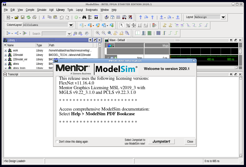

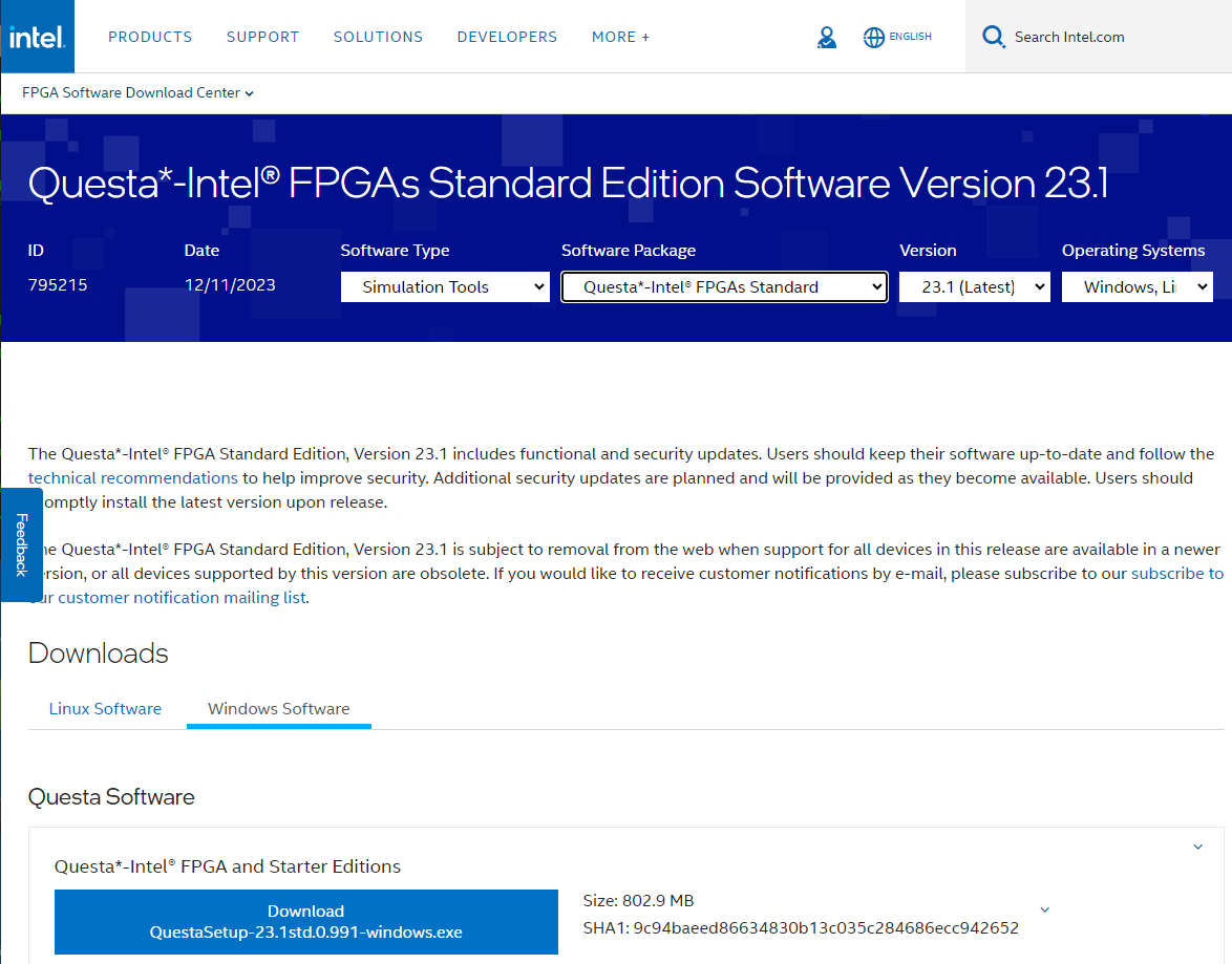


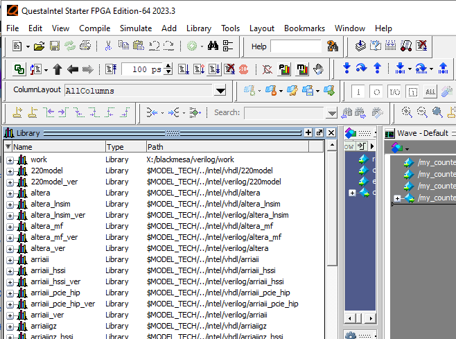
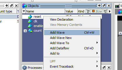
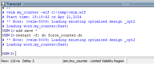
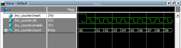
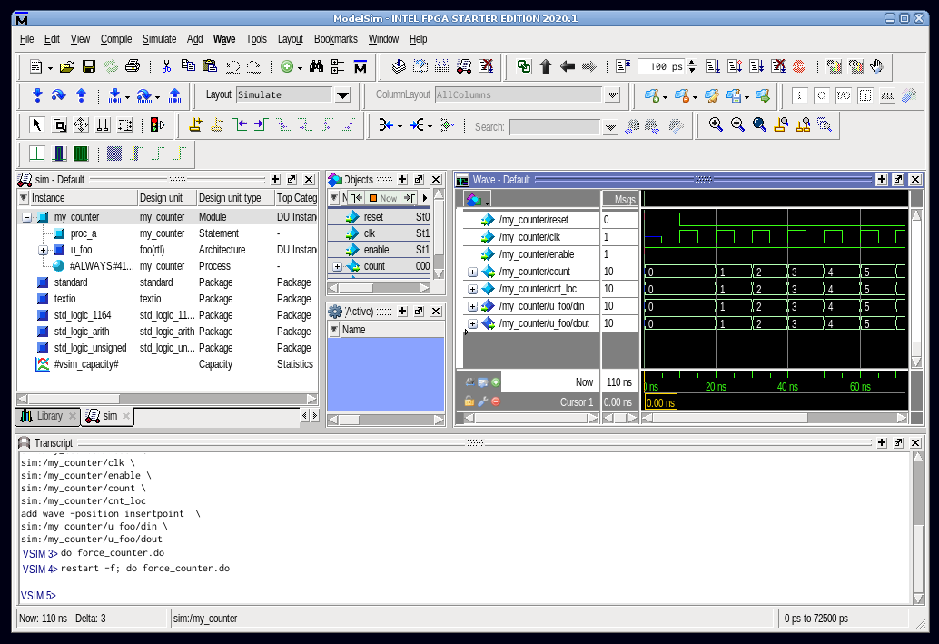
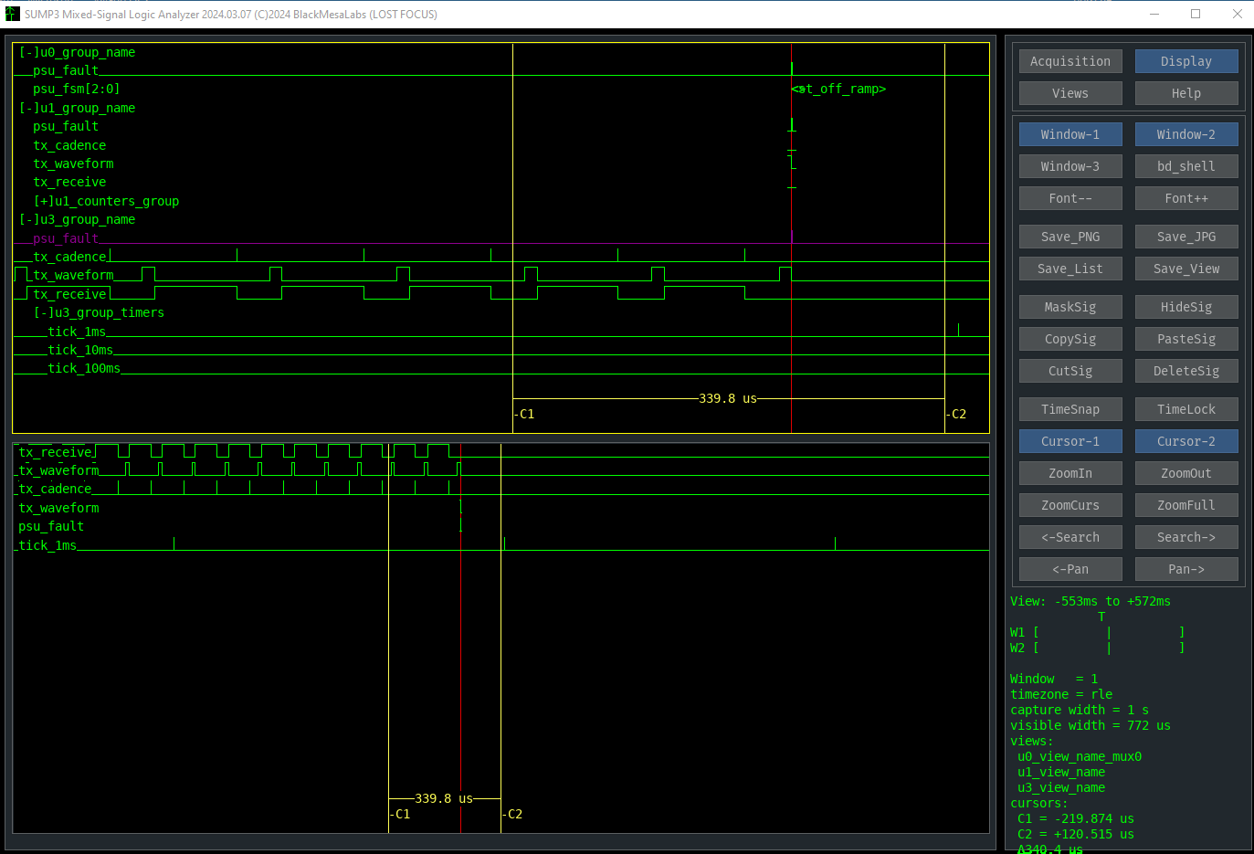
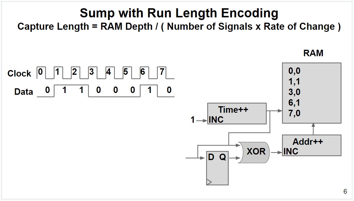
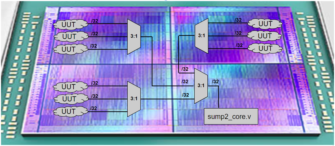
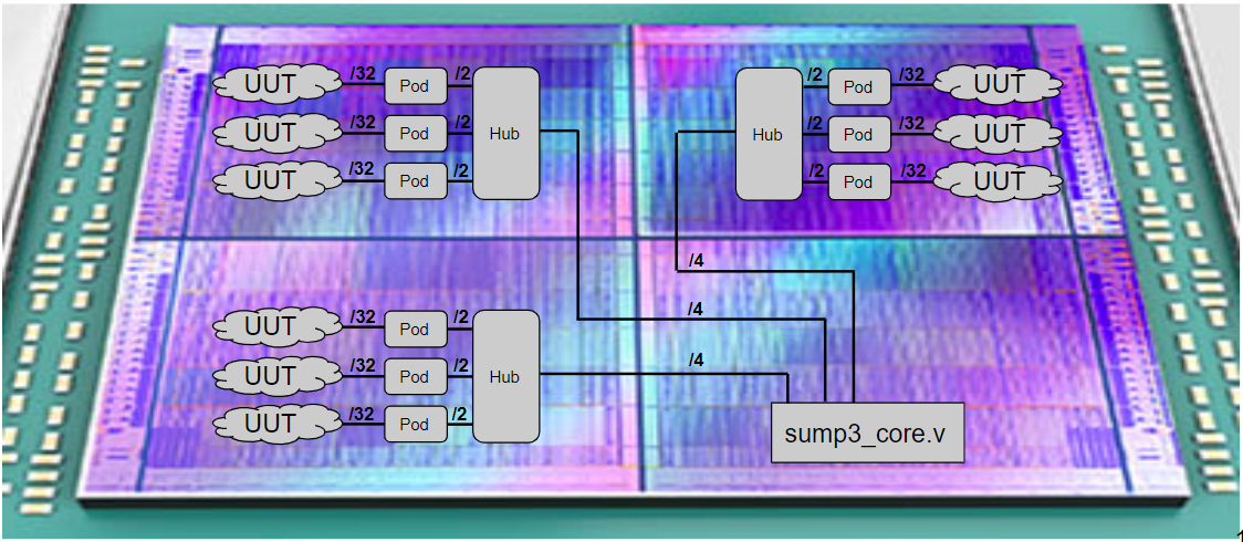
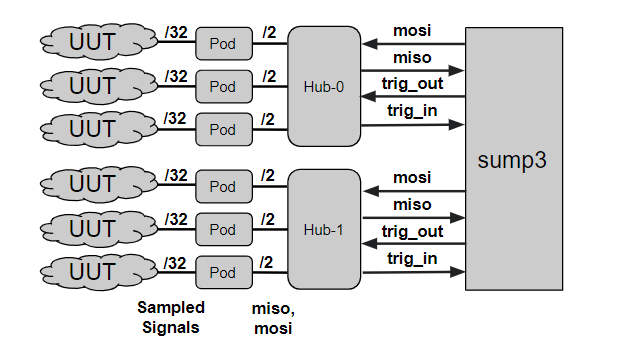
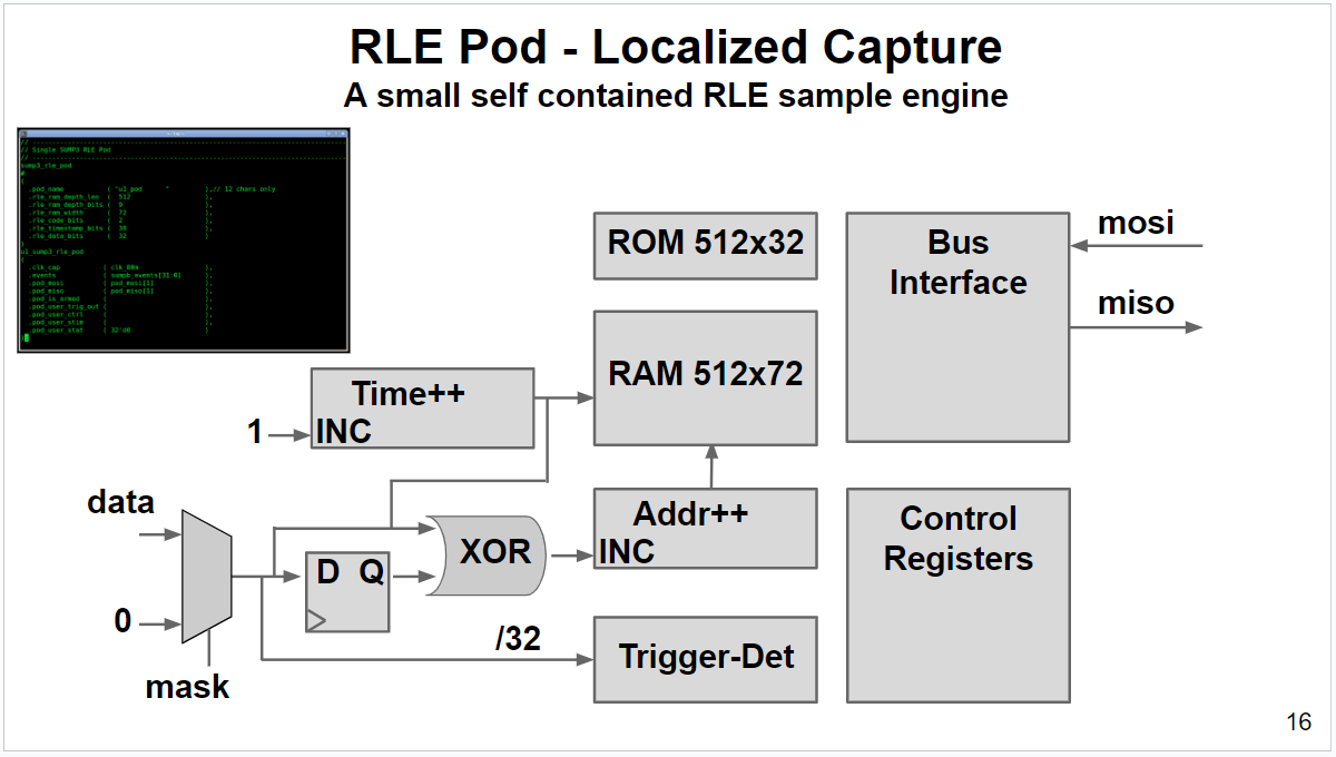
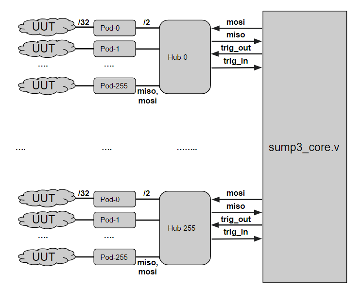
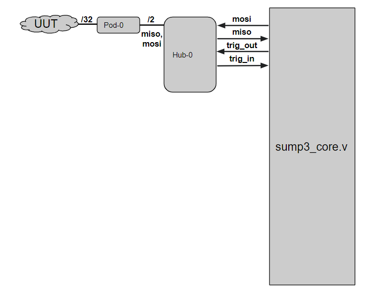
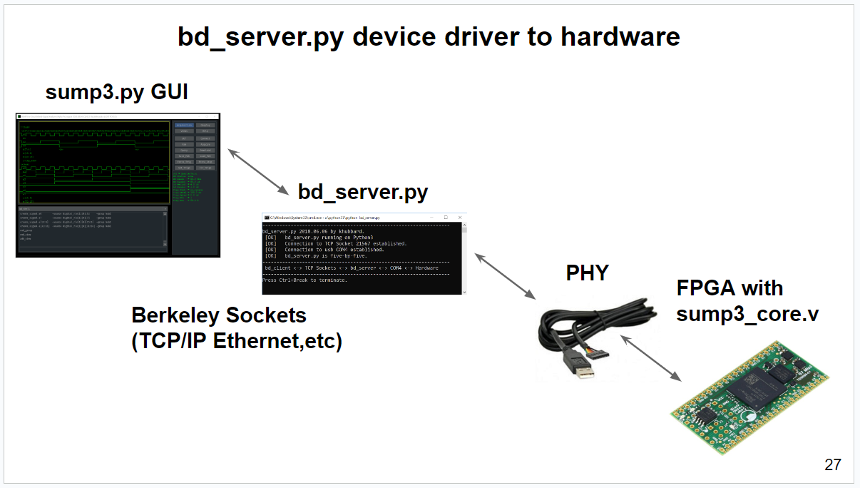
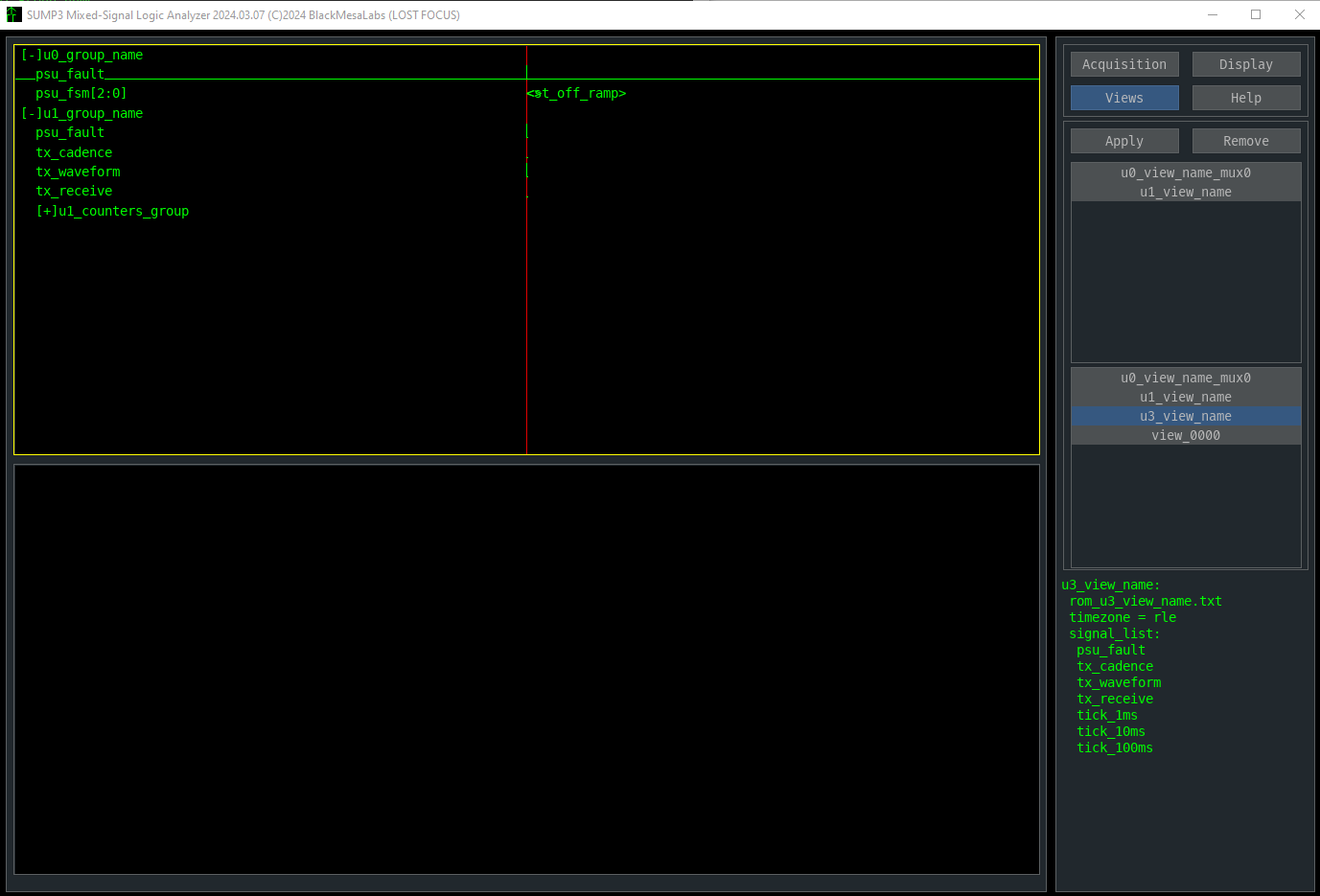
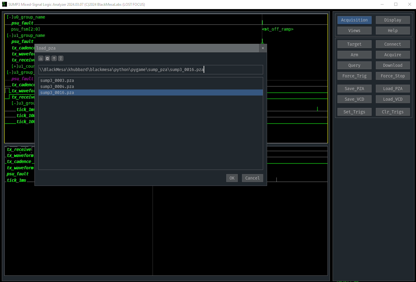
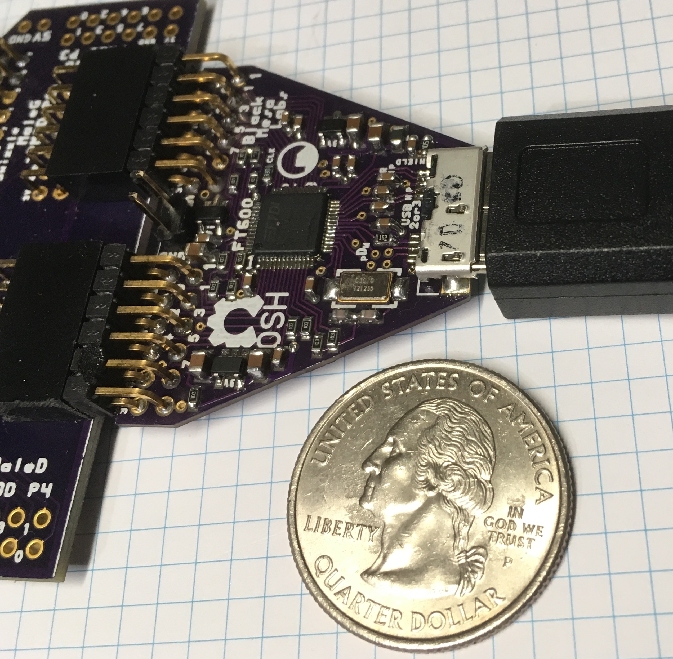
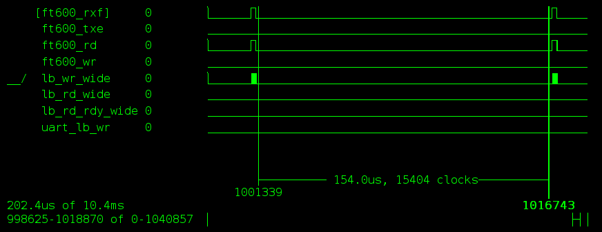
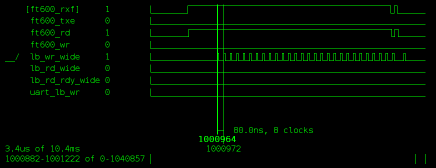
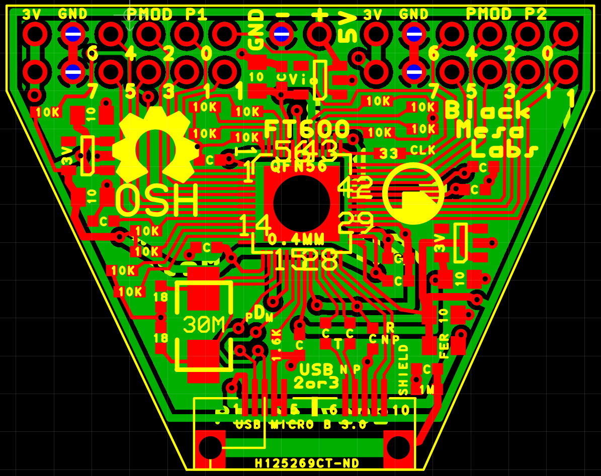
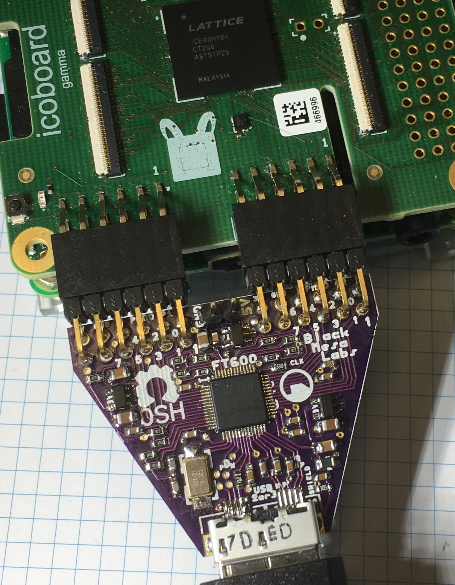
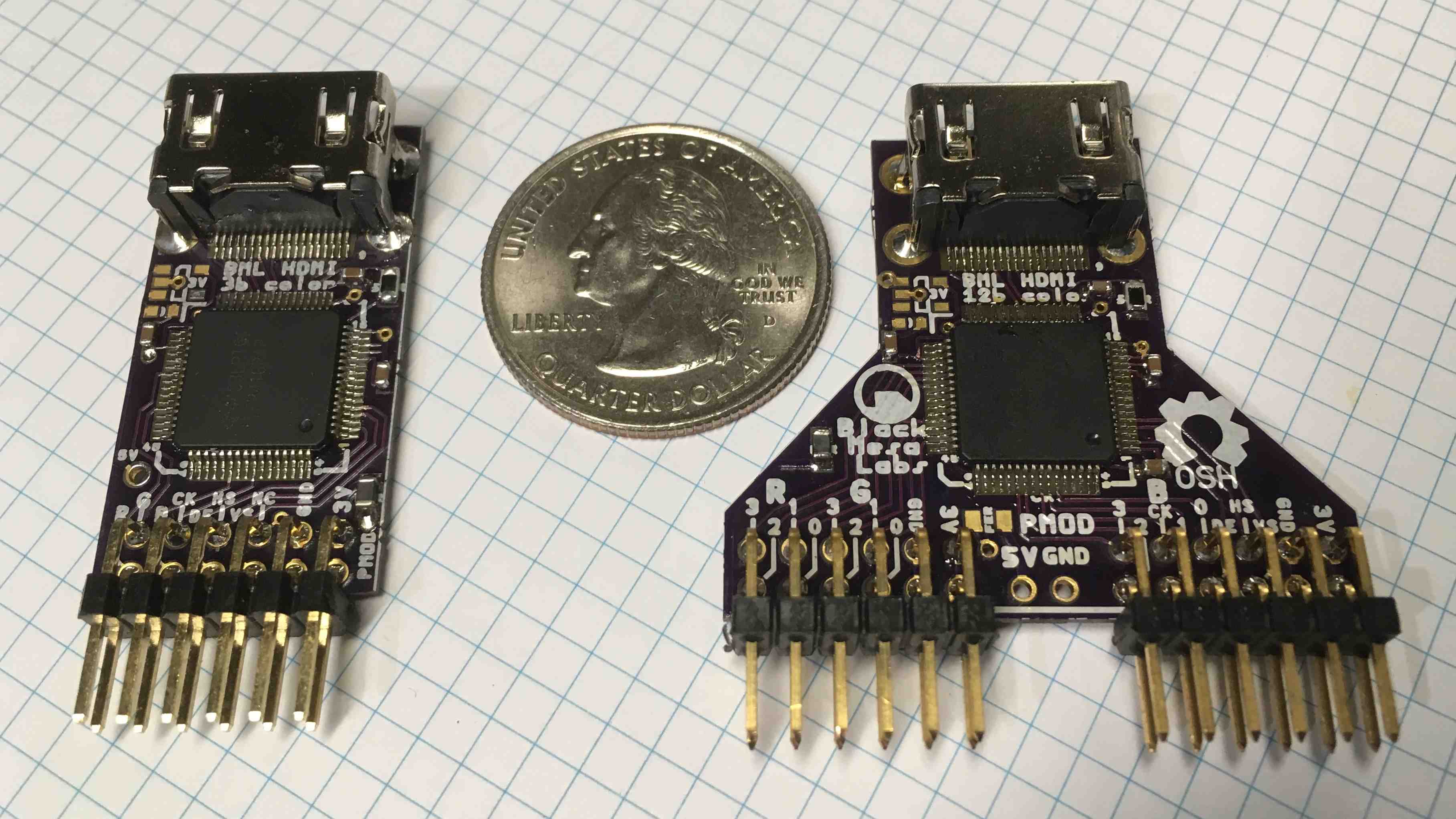
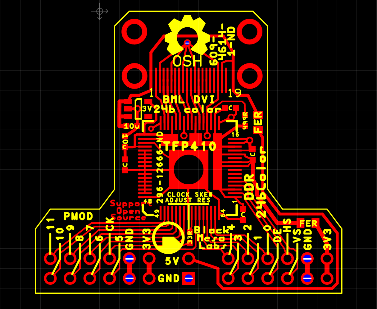
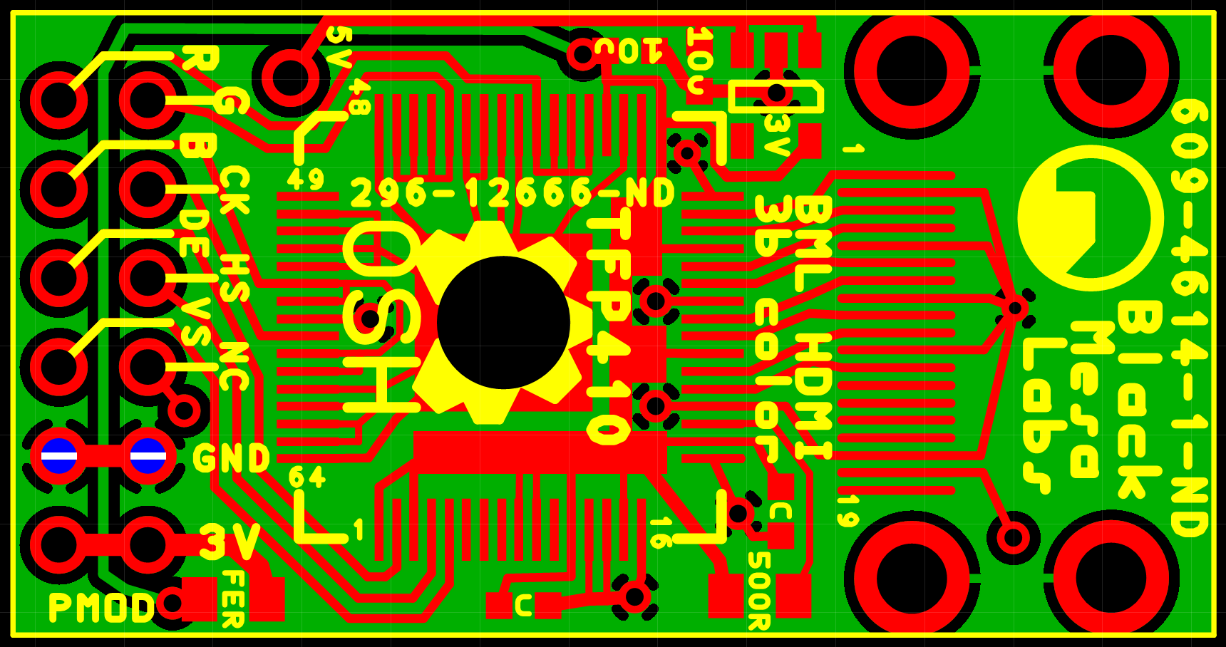
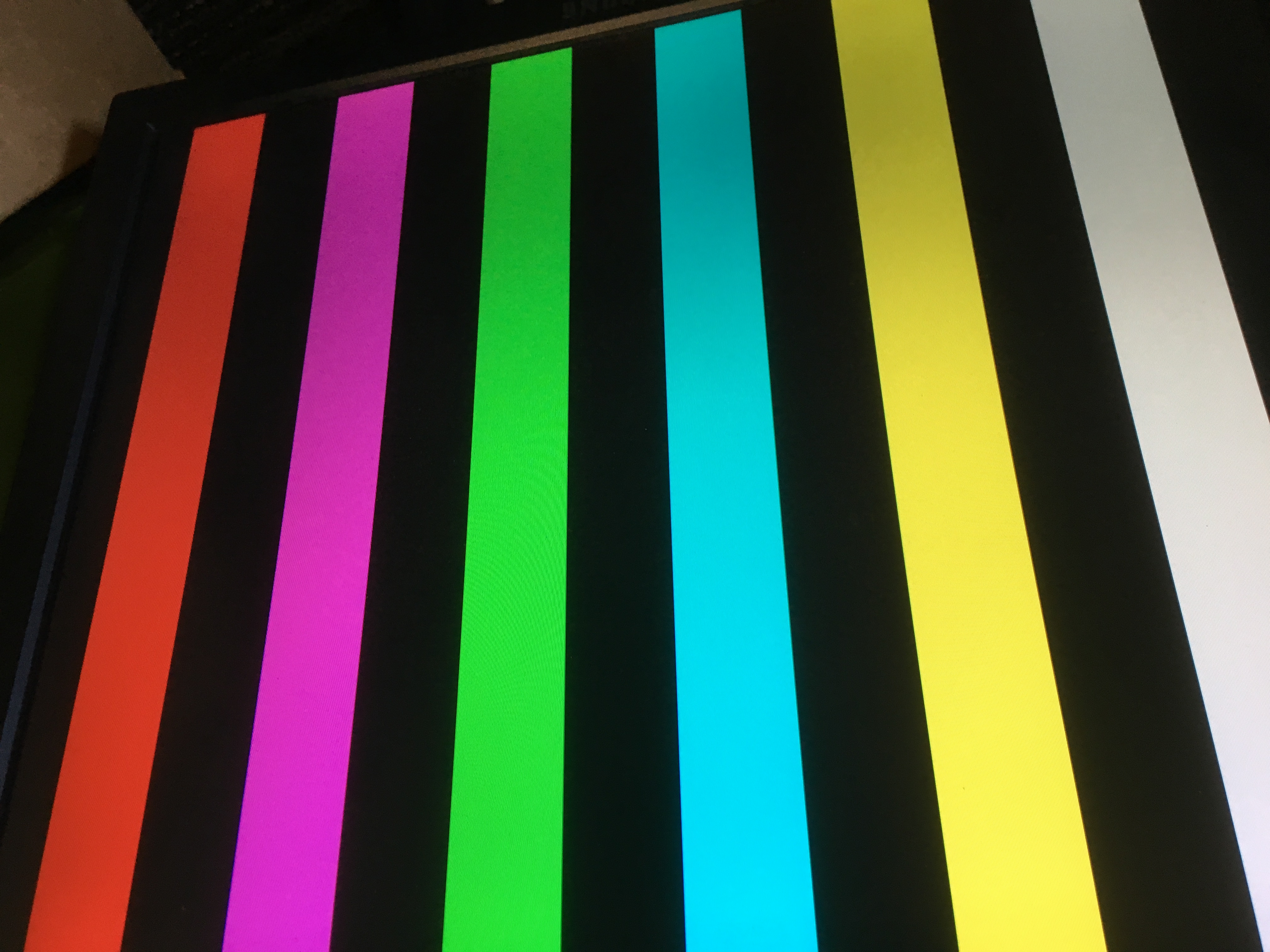
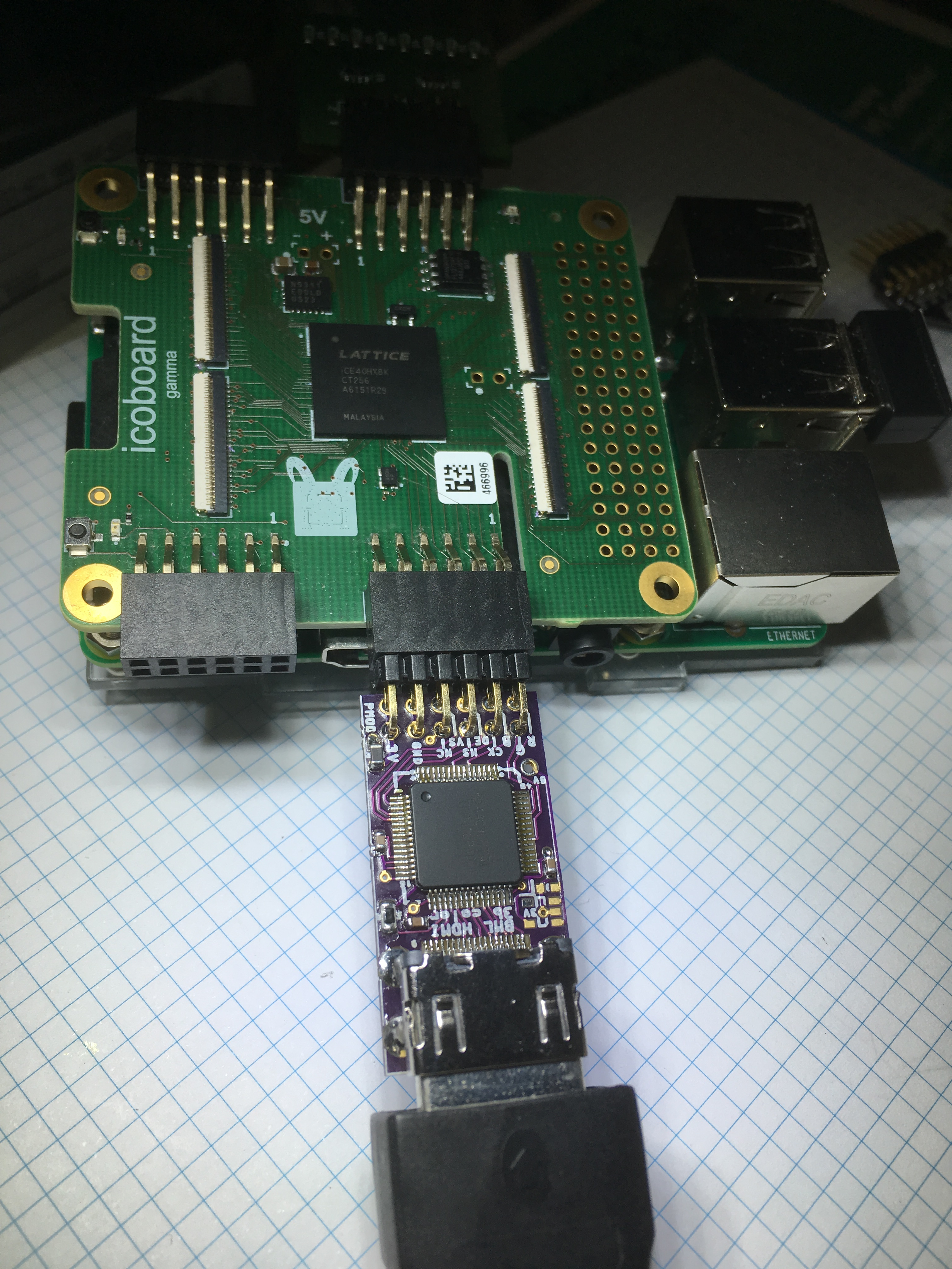
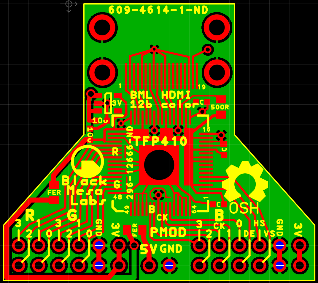
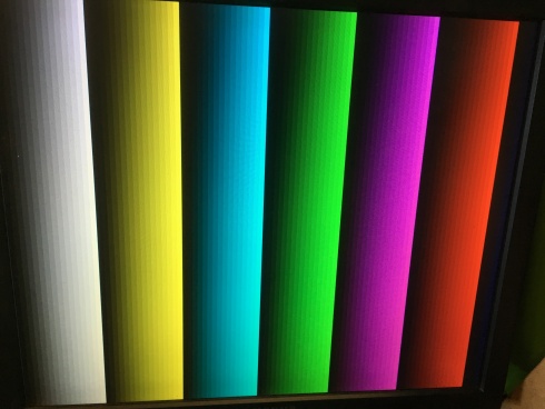
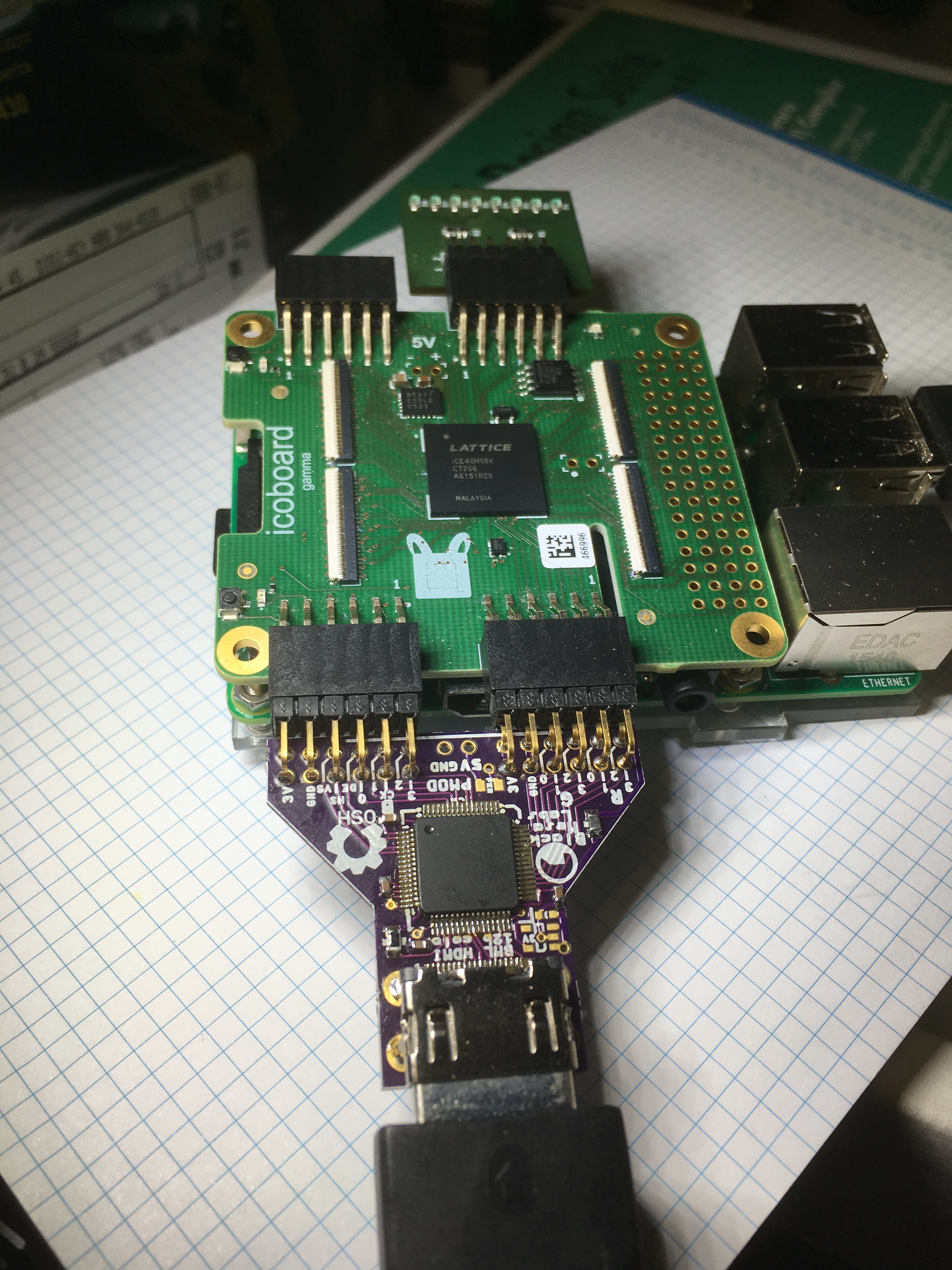
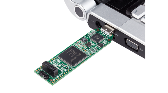
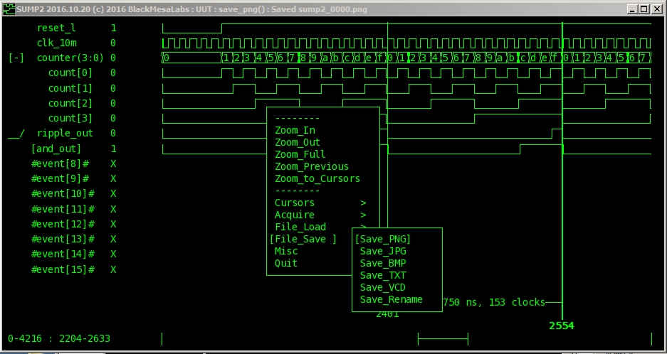
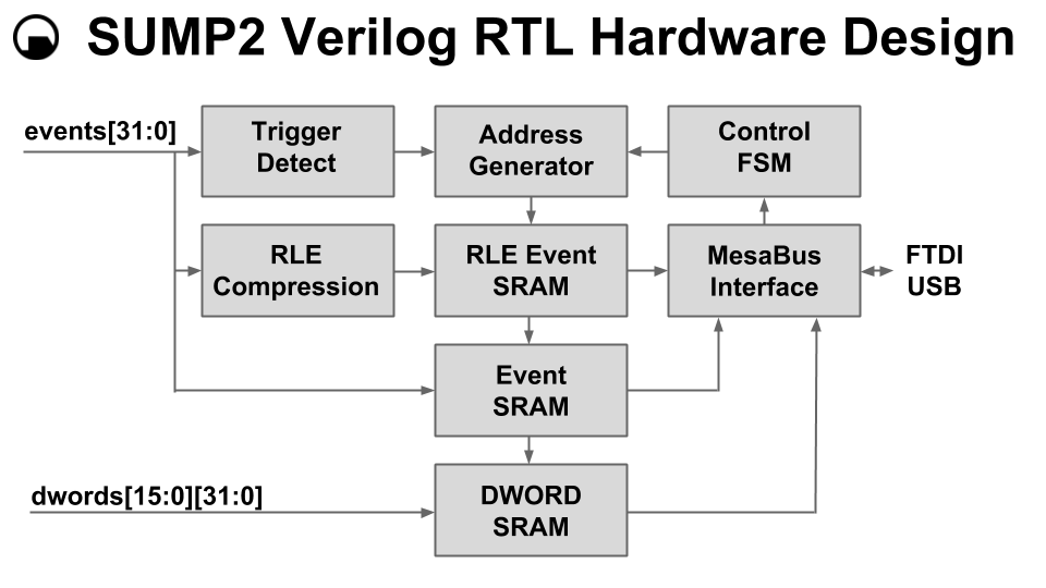
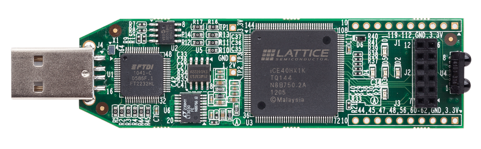
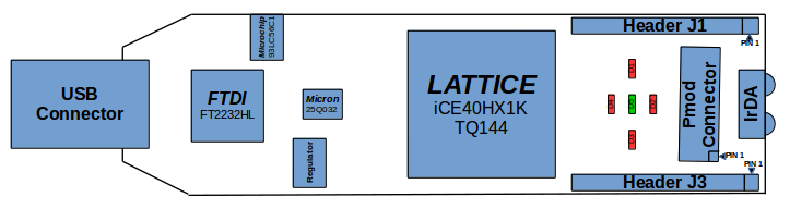
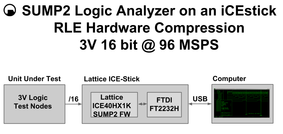
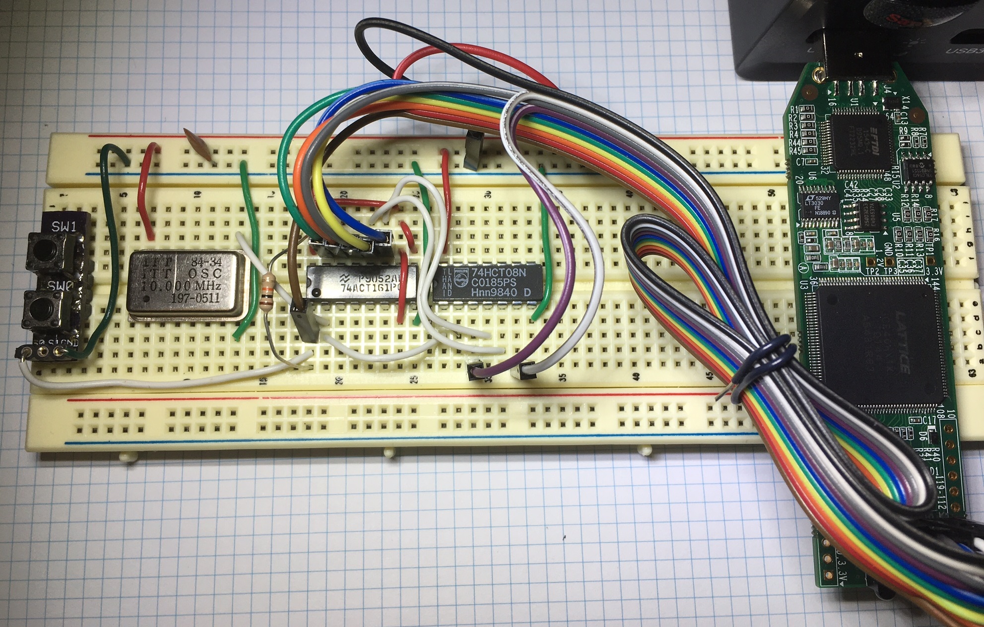
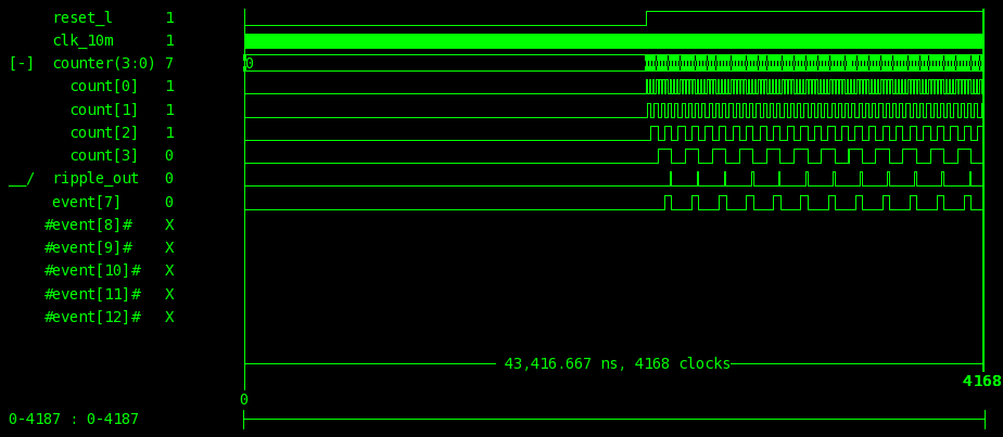
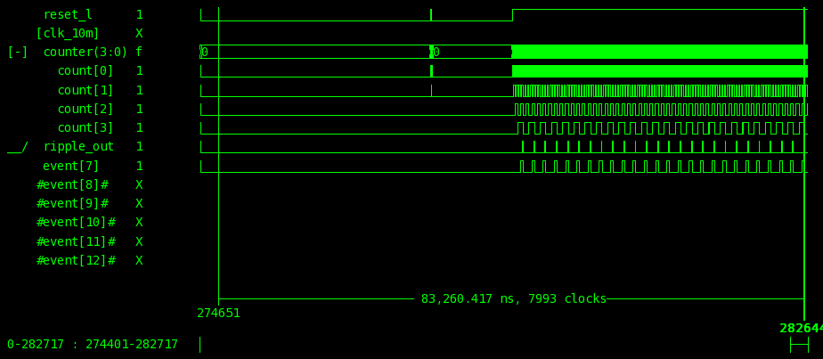
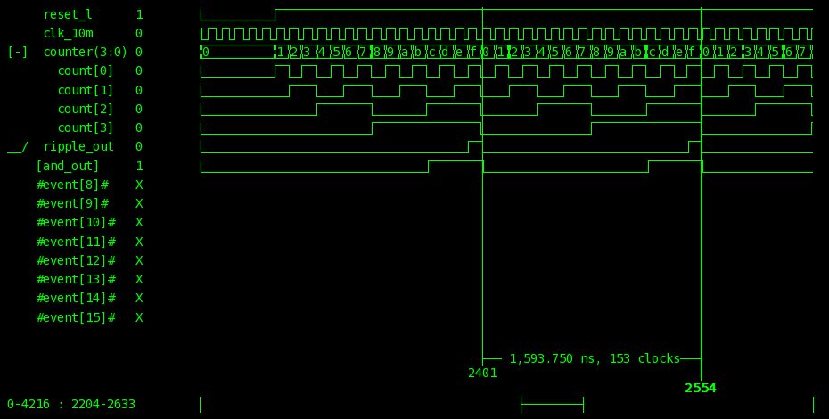

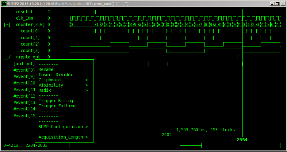
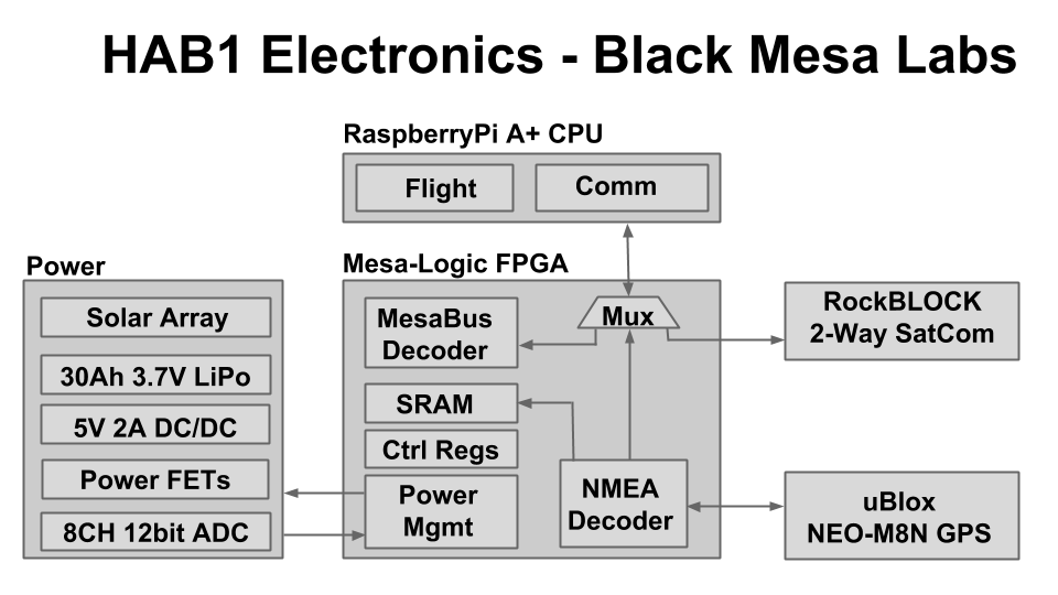
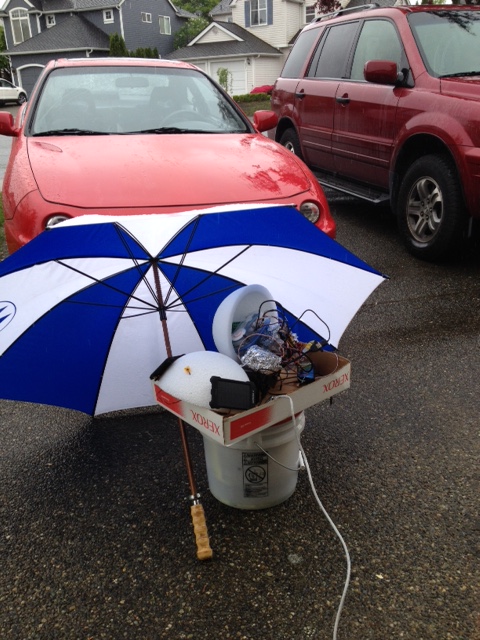
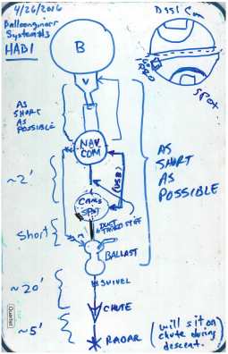
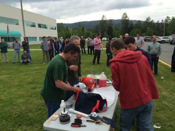
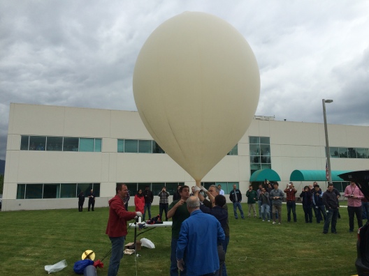
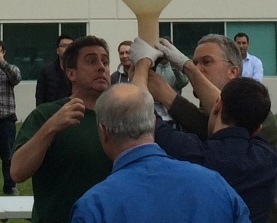 Low pressure gas expert and valve designer Dr.P and I are now both waiting for the now fully inflated balloon to attach to the valve assembly ( which is connected to the Flight Computer capsule via a 3 wire servo connection ). As the 4″ hose clamp is tightened by the fuel specialists and balloon handlers – we gasp in horror ( caught on video verbally and by the look of terror on my face here ) as we realize the small 3 pin 0.100″ pitch SIP connector connecting the Flight Computer to the Valve servo assembly is not only disconnected – but the pins are bent. SIP connectors are great – I use them all the time – but they really don’t like to be bent. These were dangerously close to the hose clamp. Bend SIPs once – maybe, bend them twice – and they break off. Do we abort the launch? Is there time to solder a new SIP connector on the leads running 12″ to the flight computer? No – the balloon is filled and ready to go. The balloon handlers in their special balloon protecting gloves are now responsible for keeping the balloon untouched from any foreign objects before flight – it just is not feasible to abort this late in launch with the balloon already inflated.
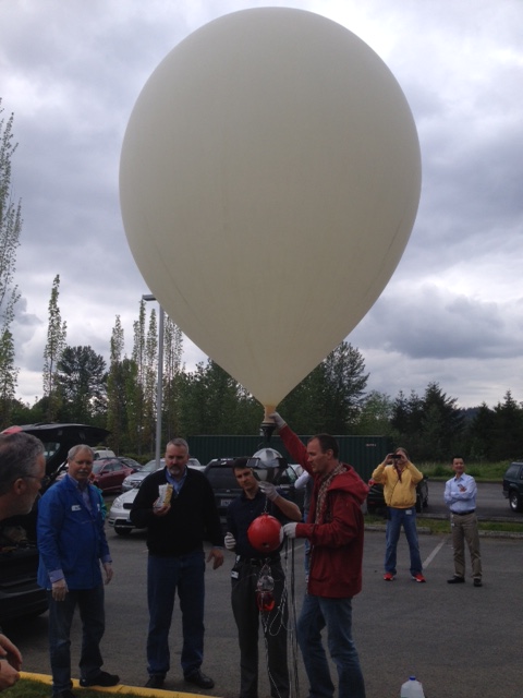
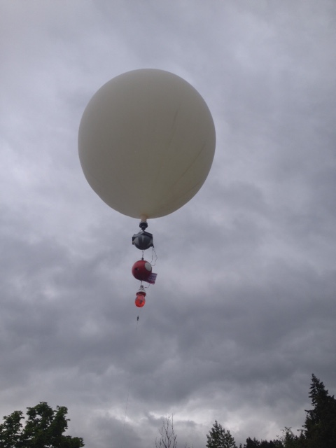

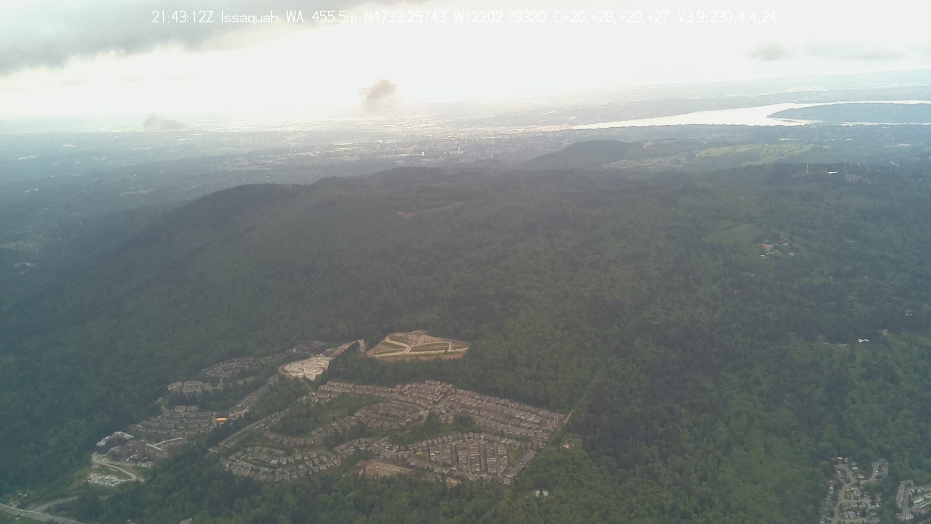
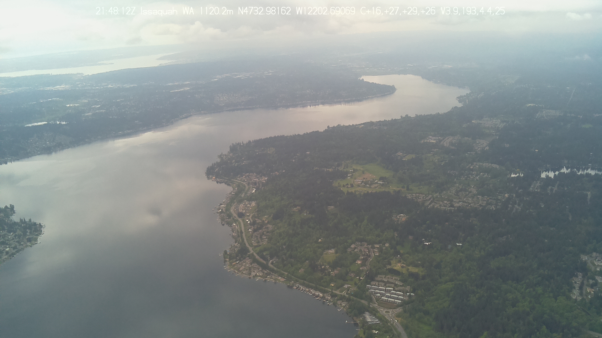
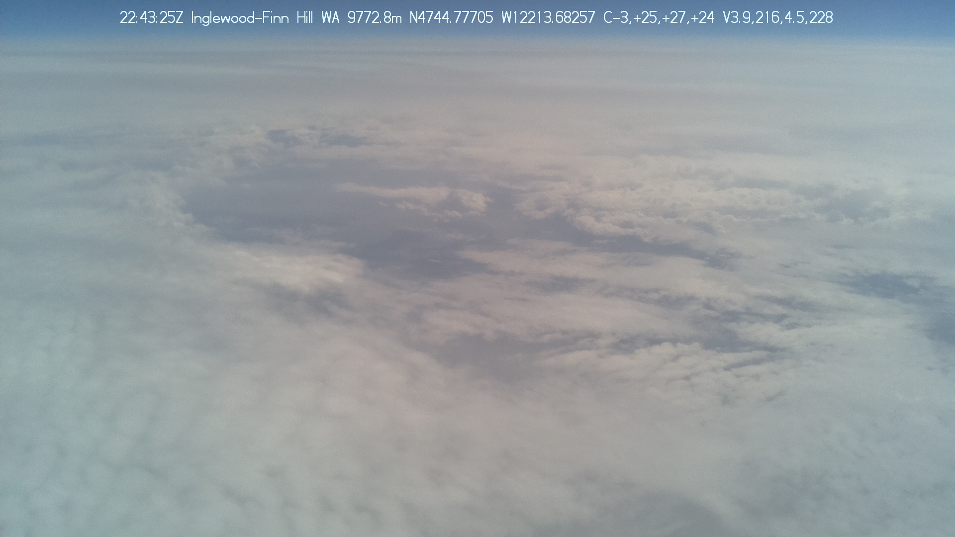
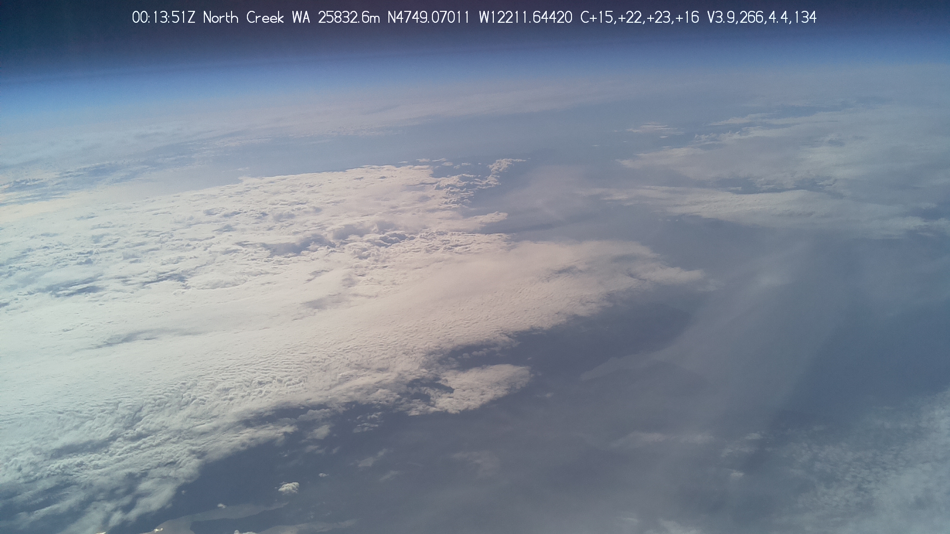
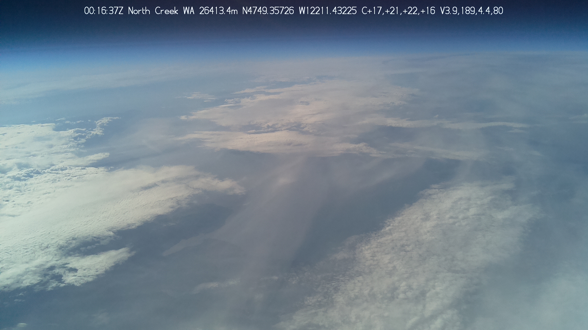
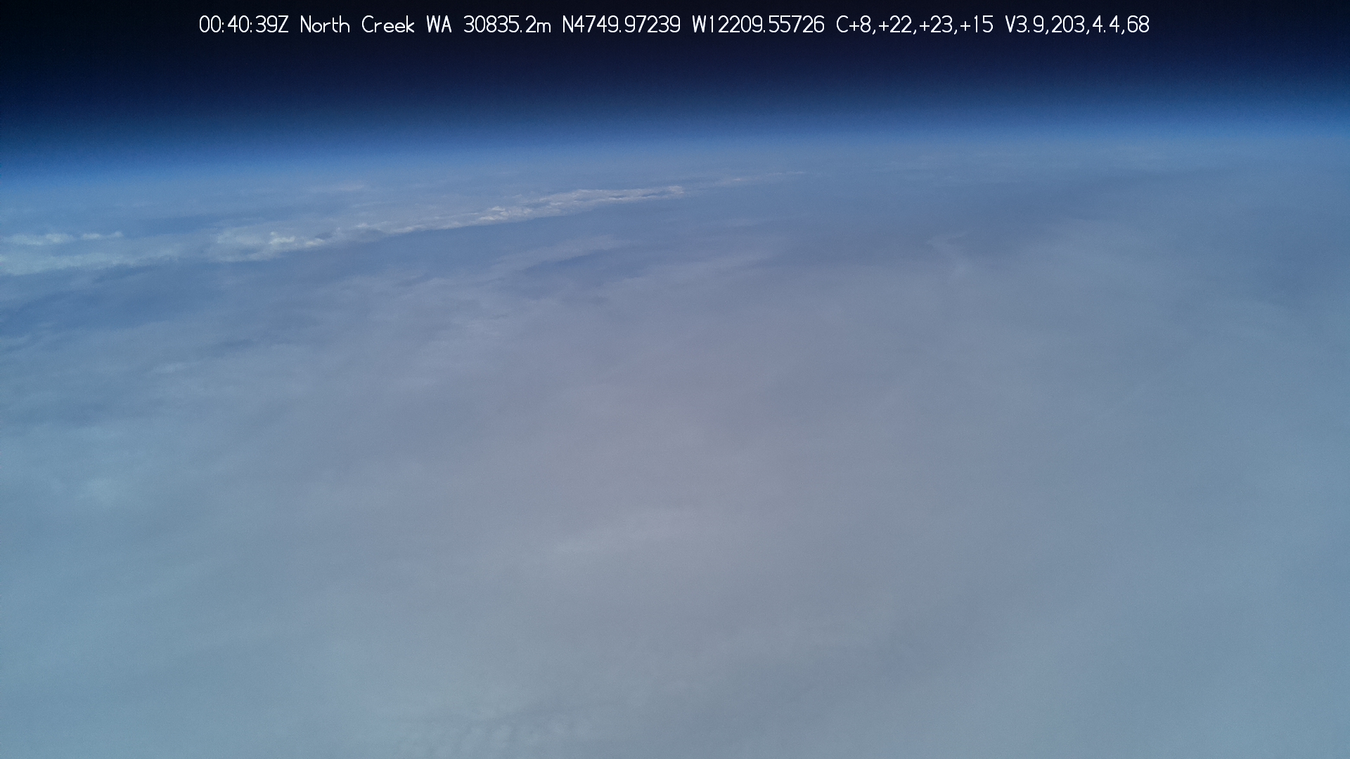


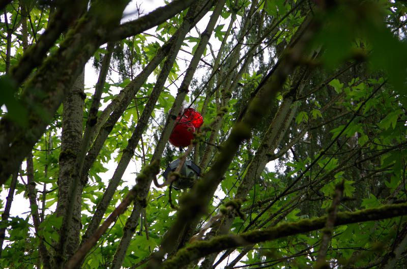
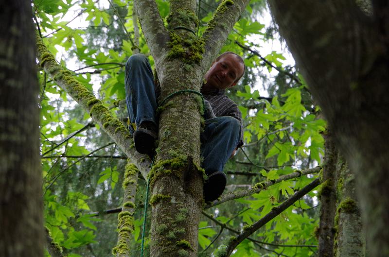
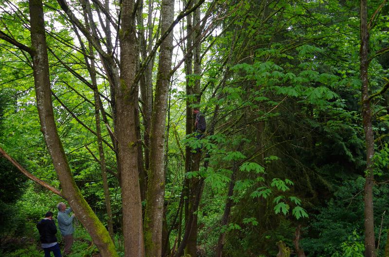

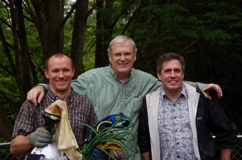
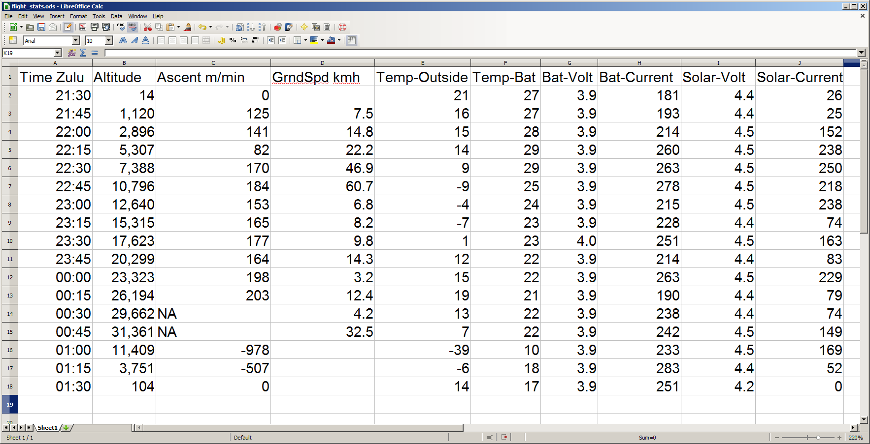
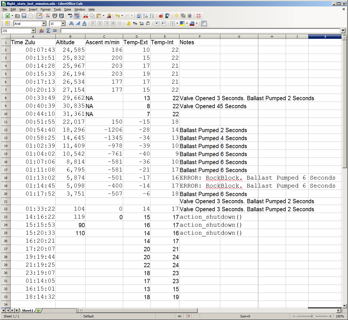
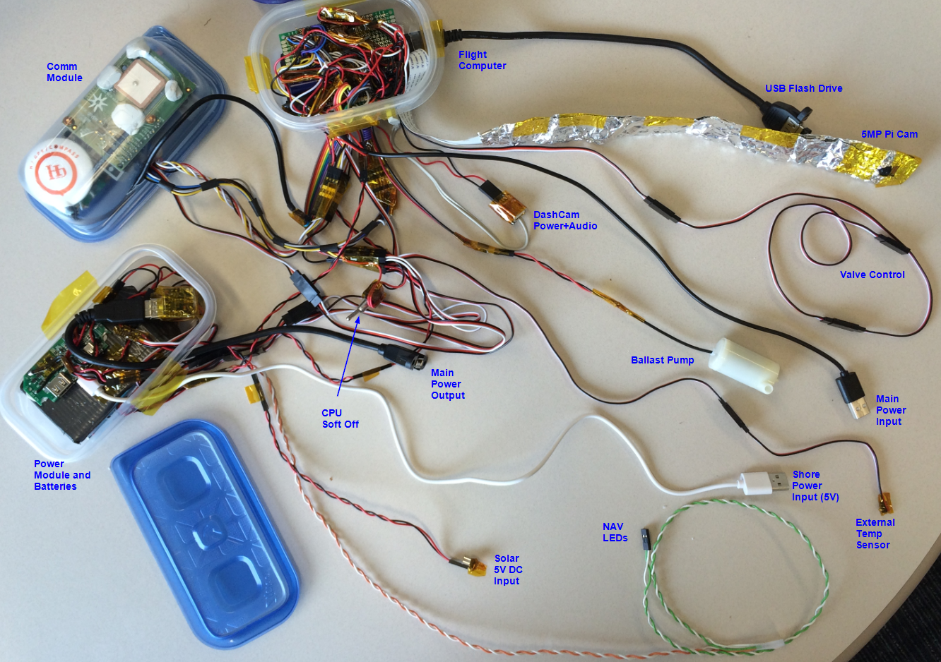
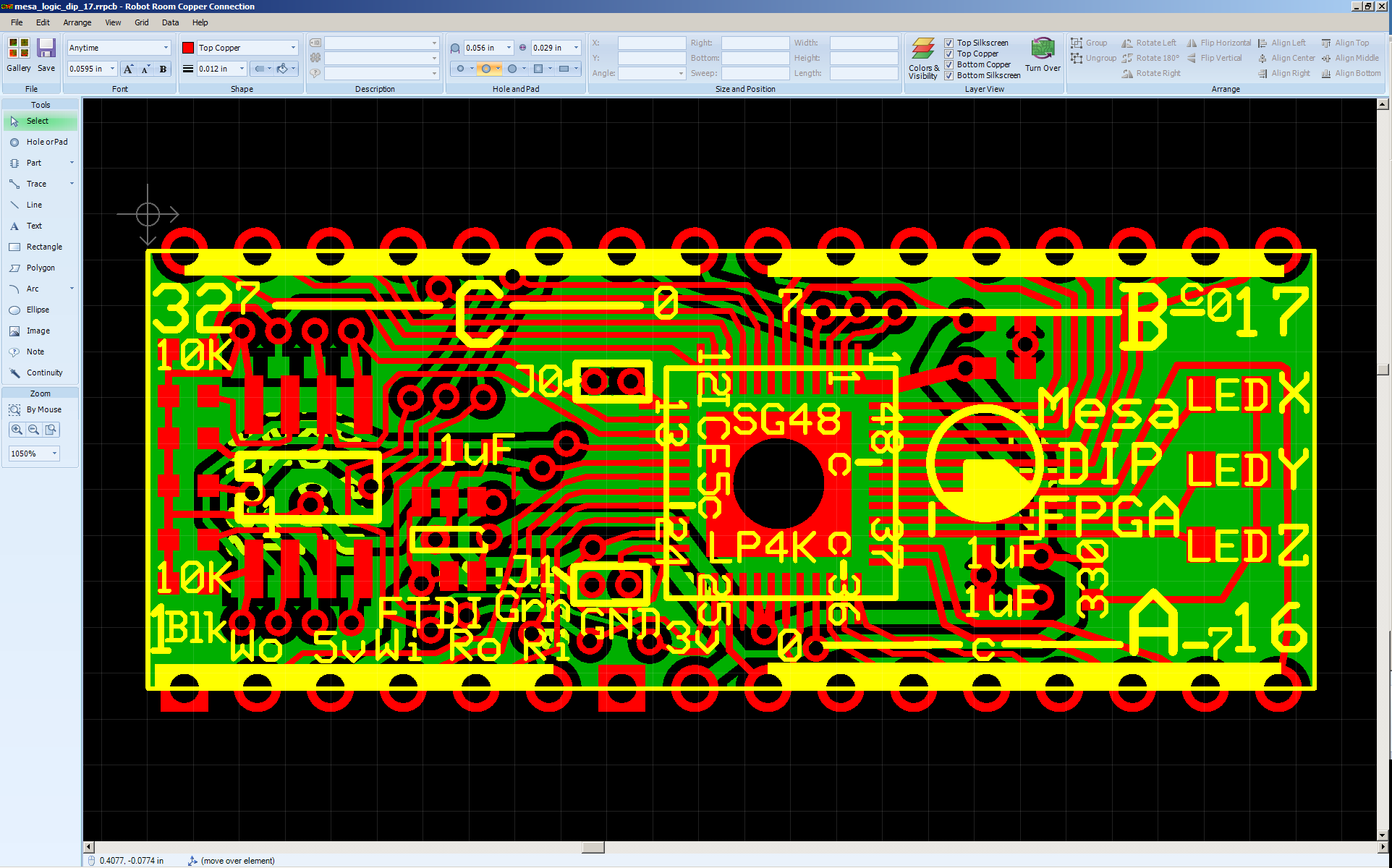
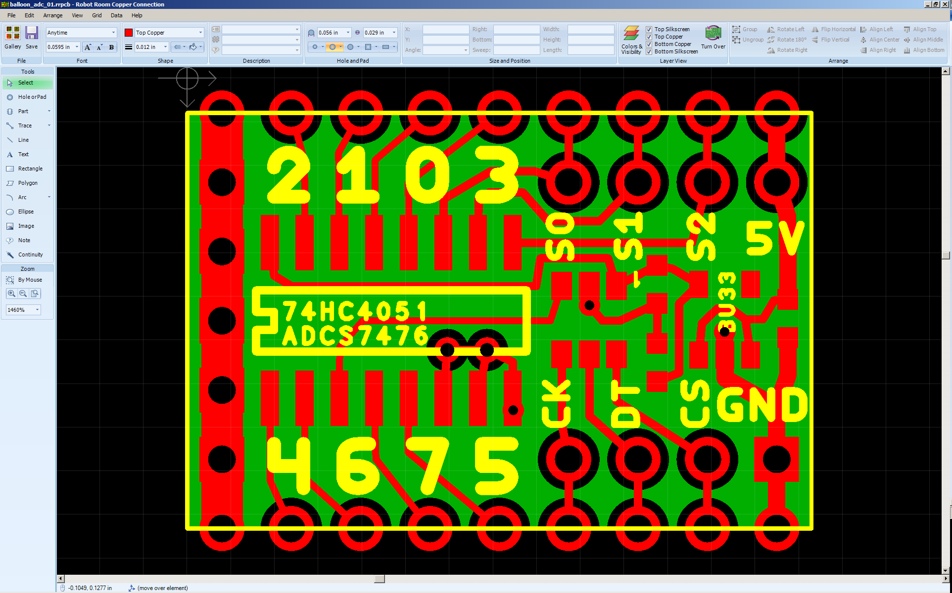

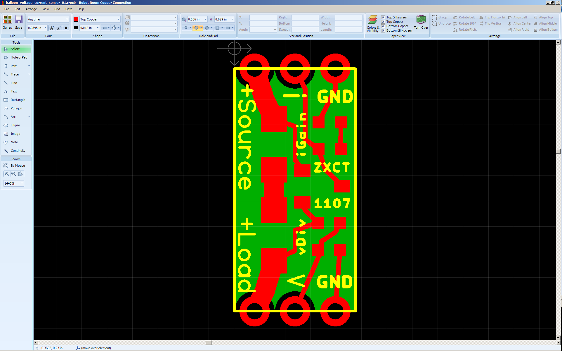
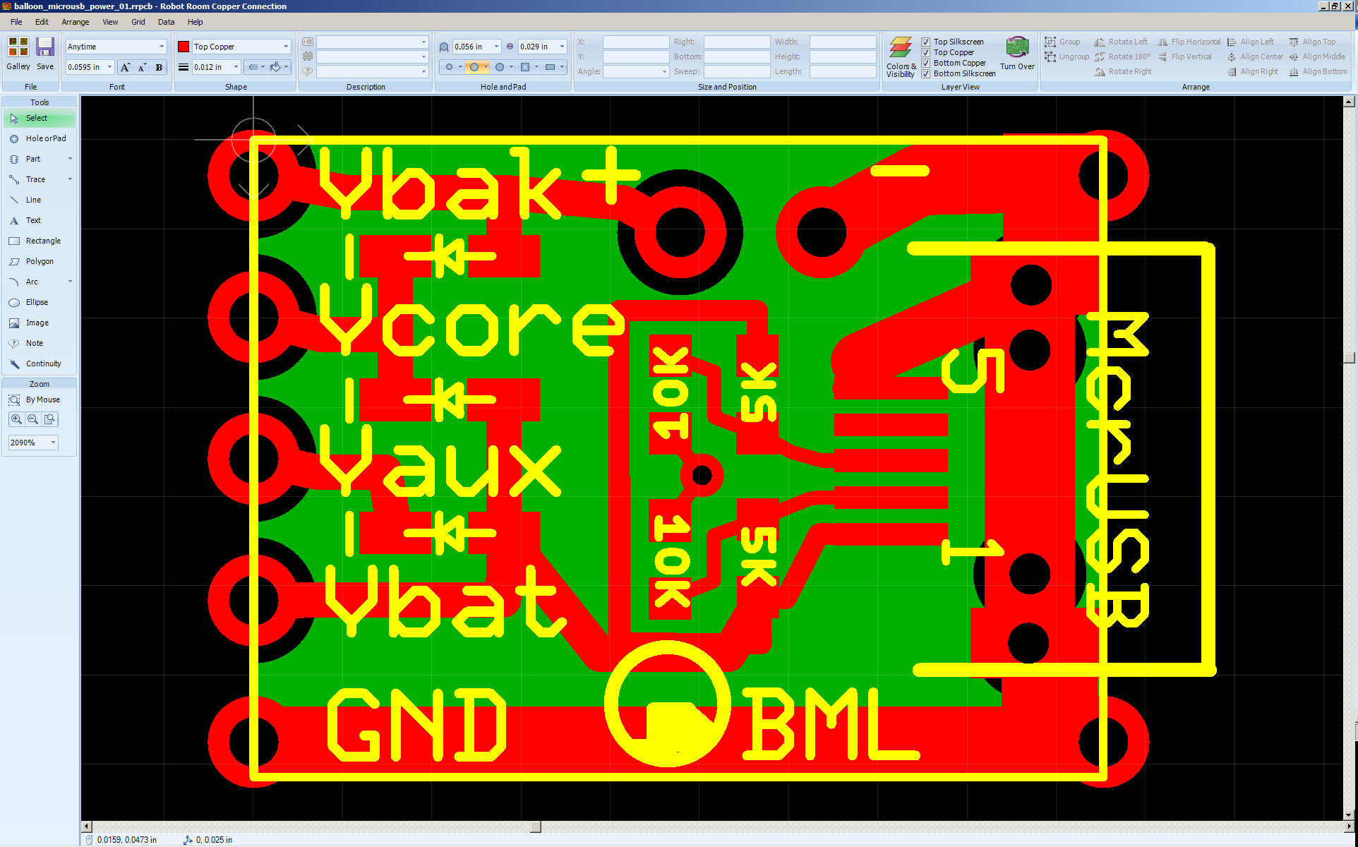
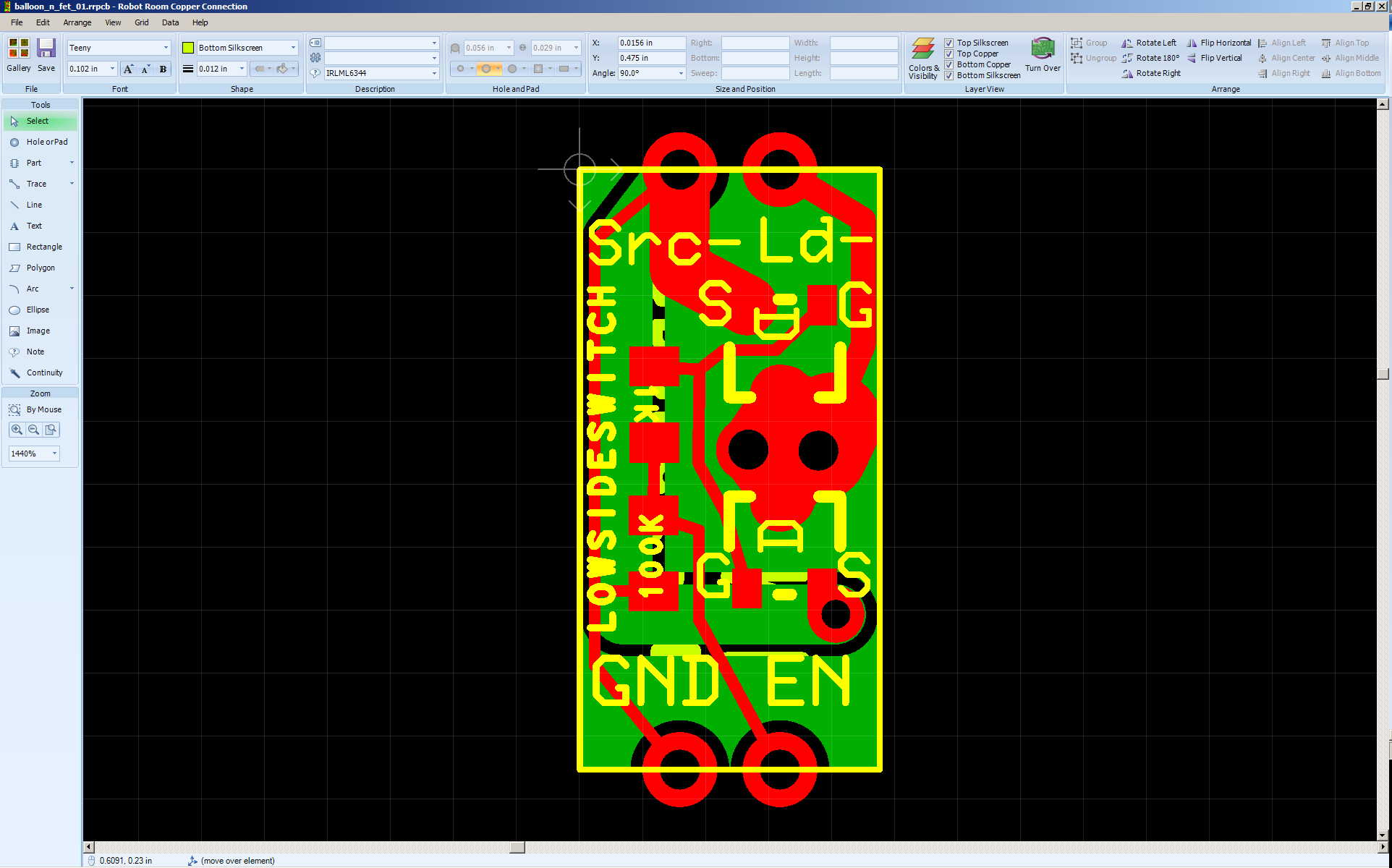
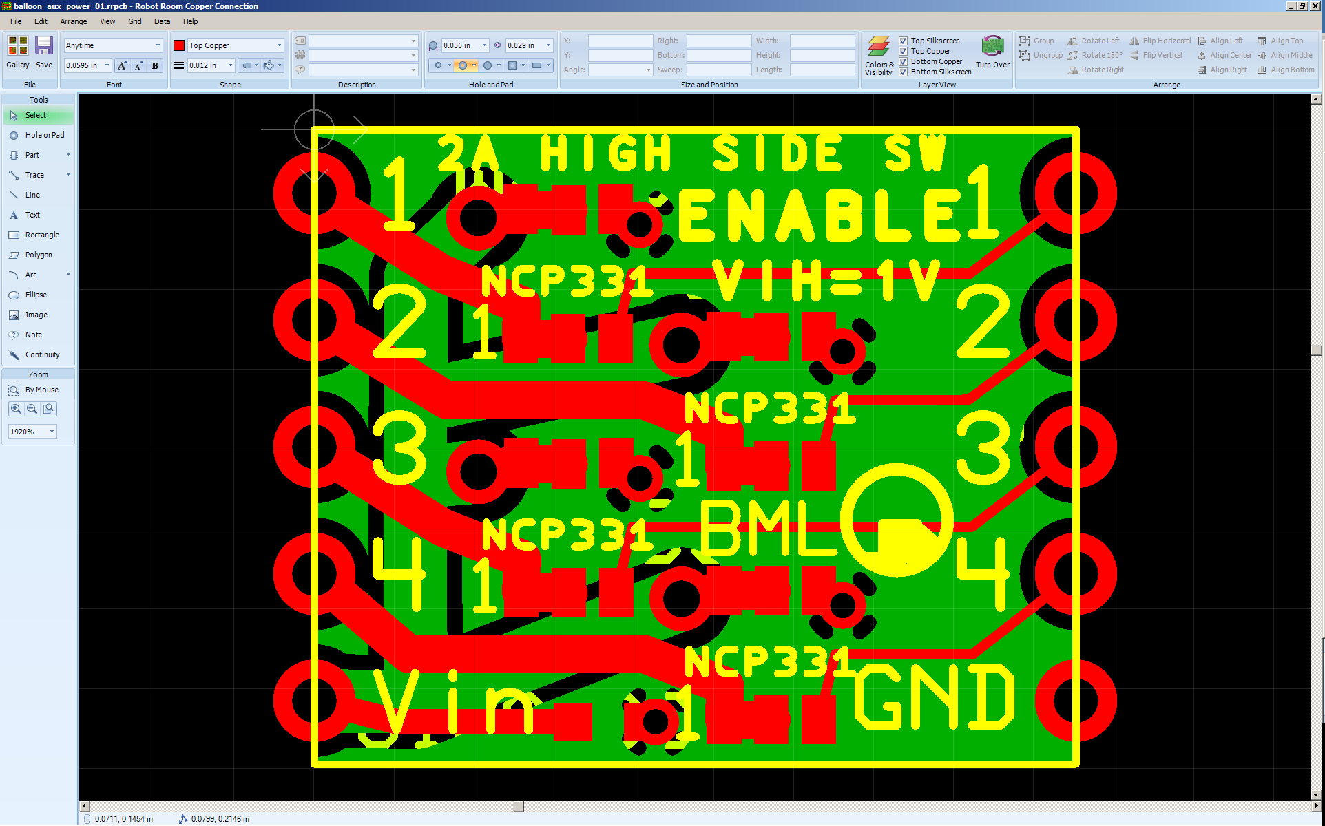
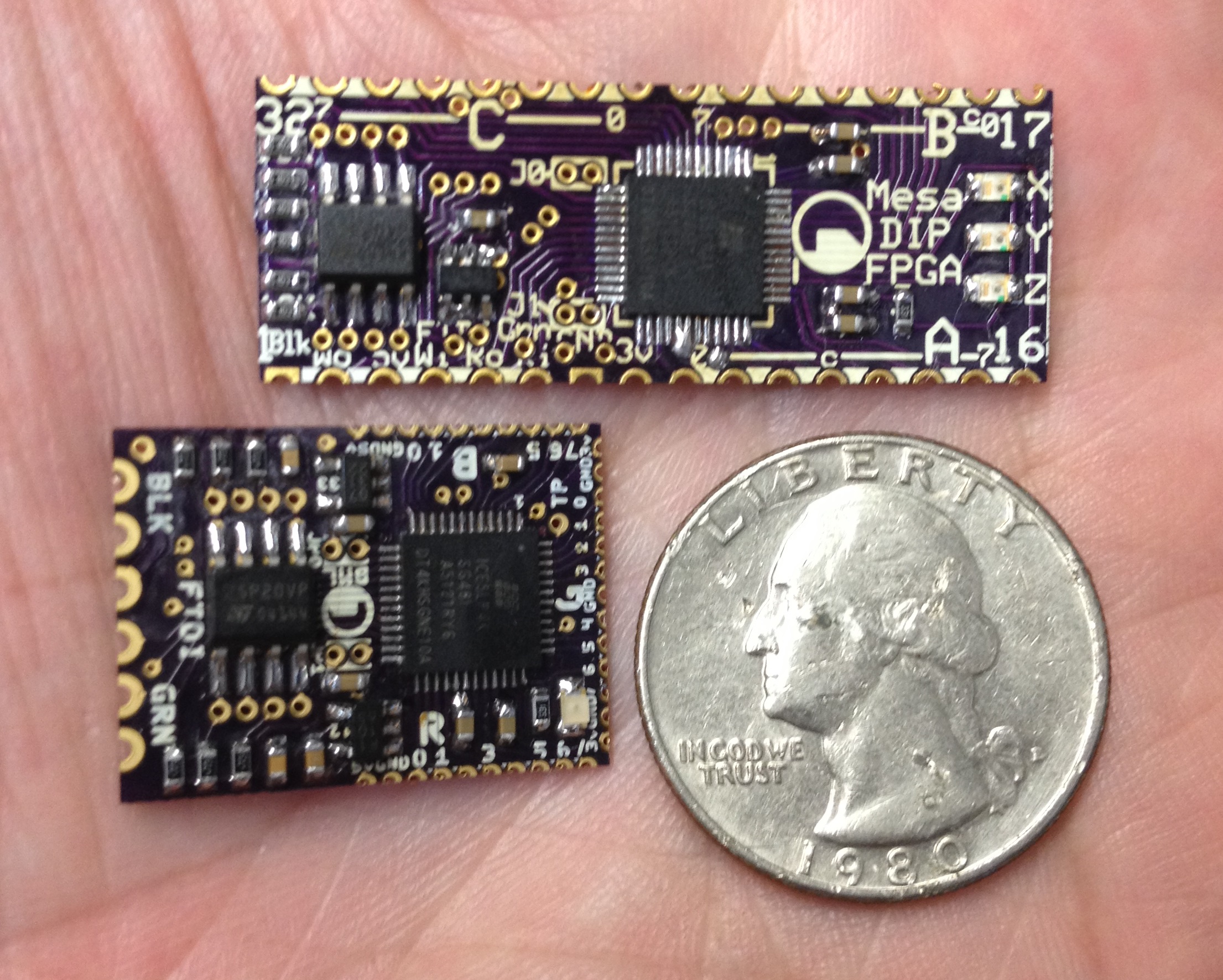
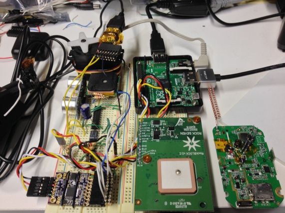
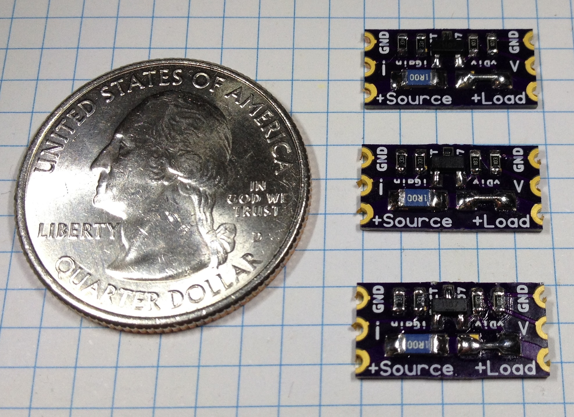
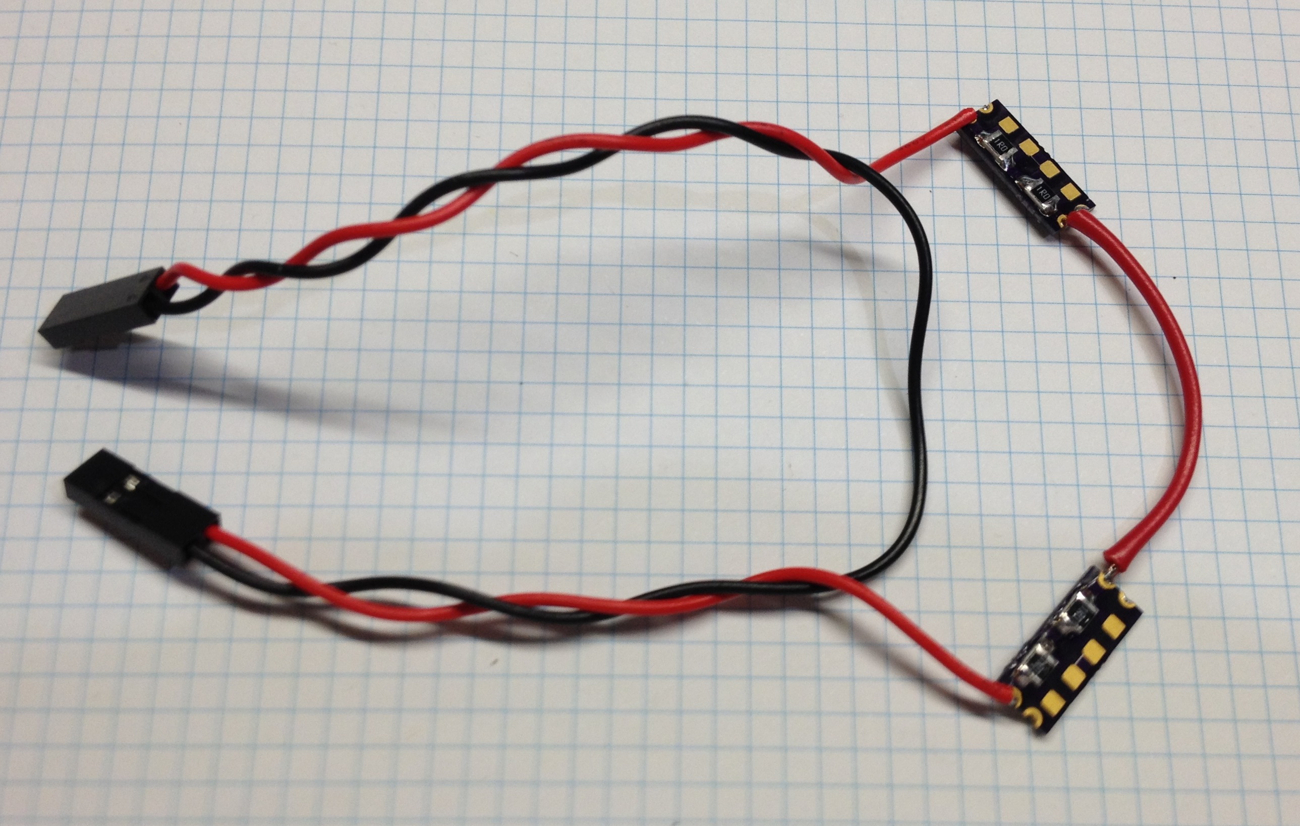
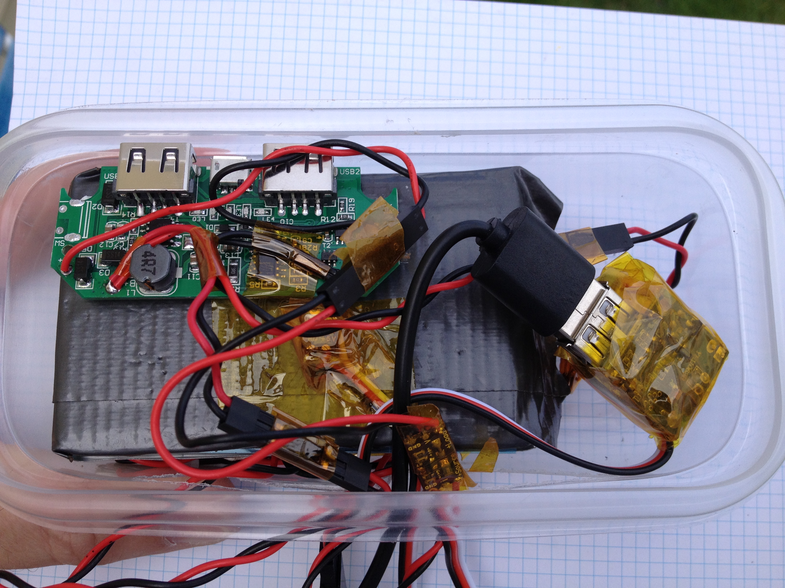
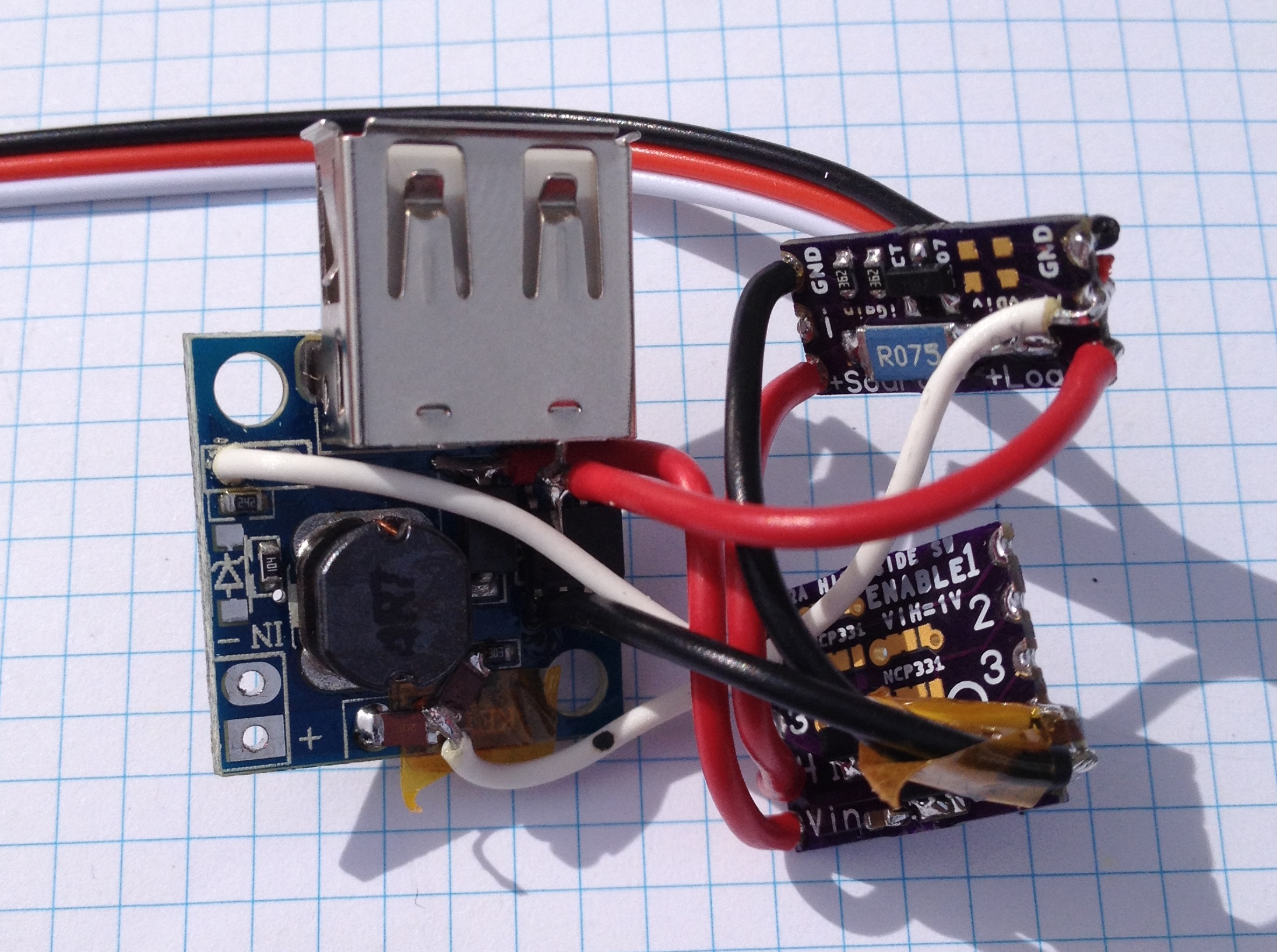
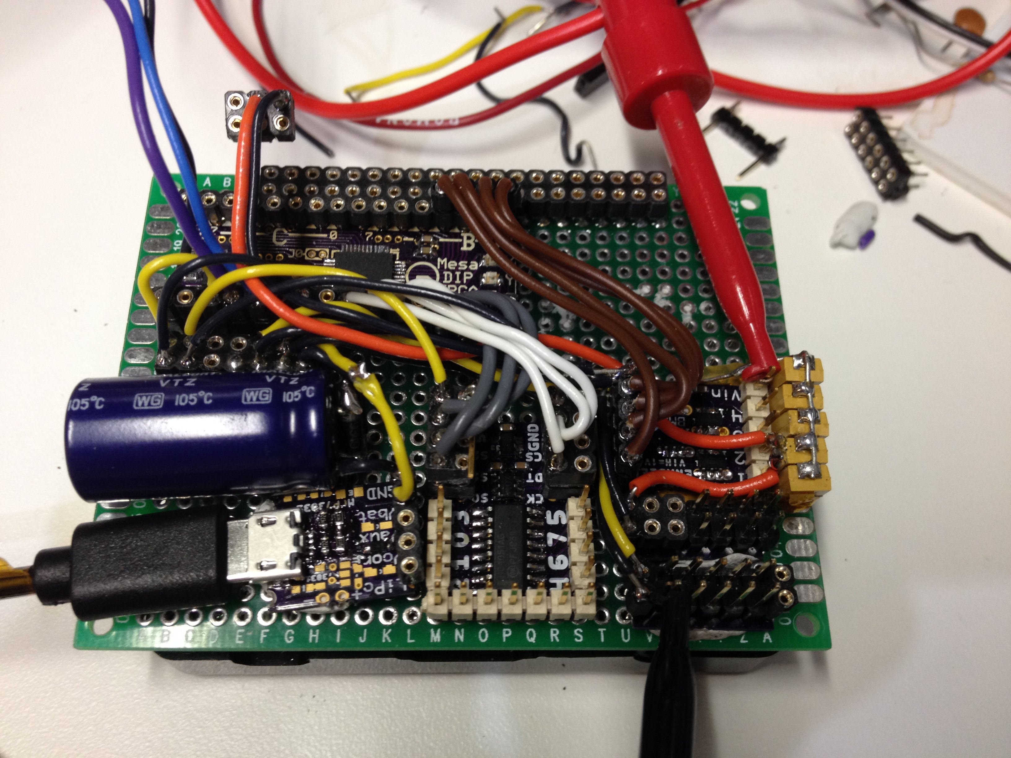
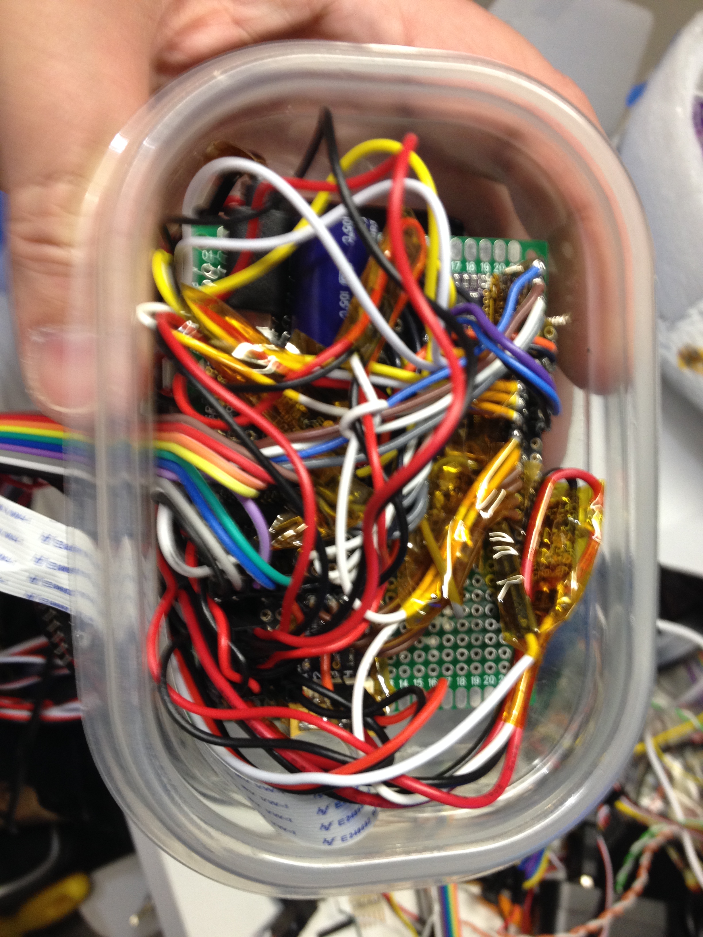
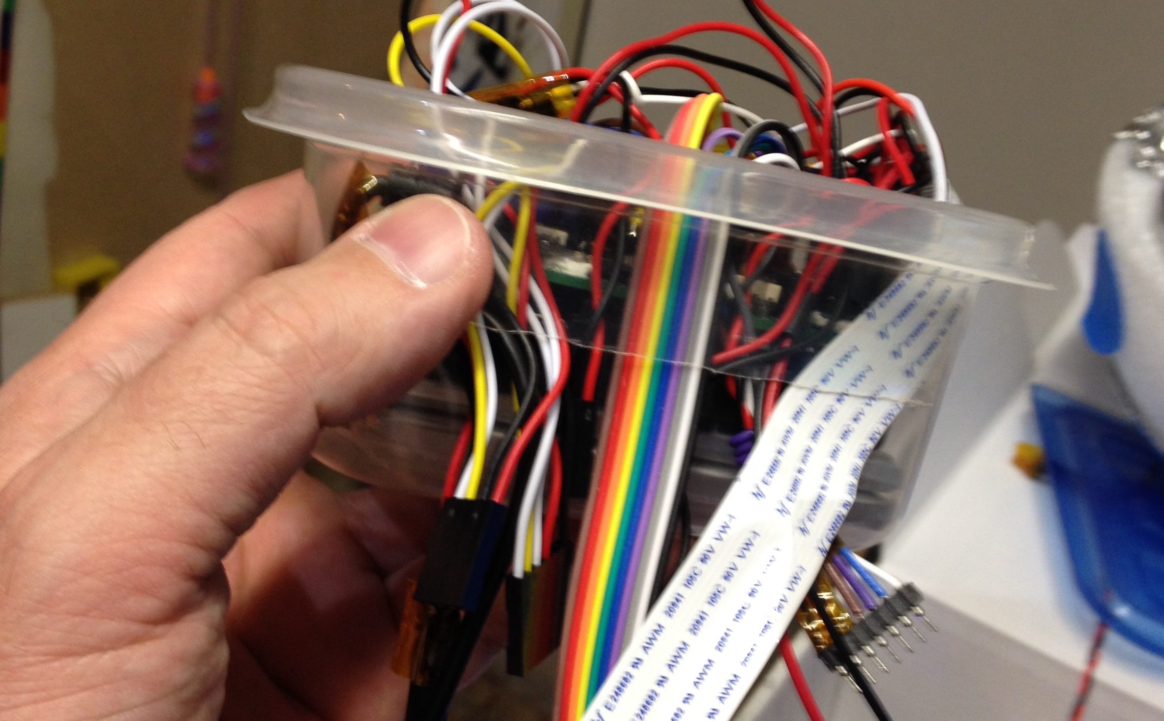
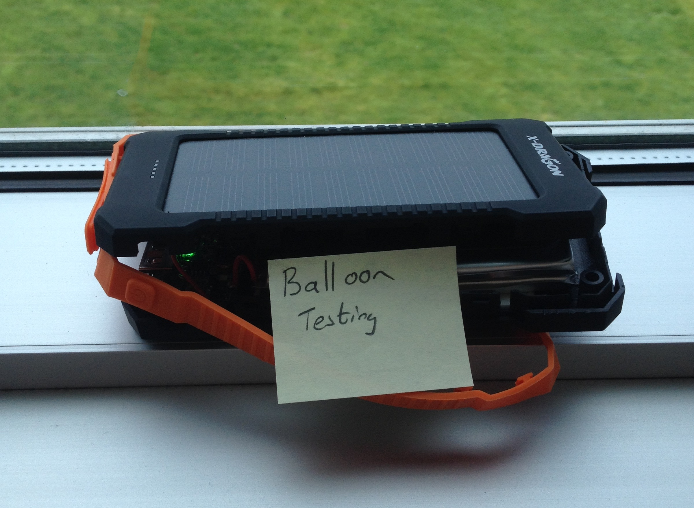
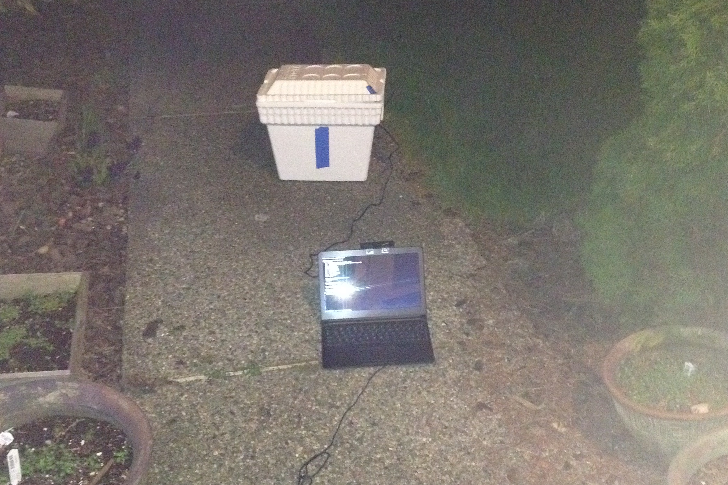
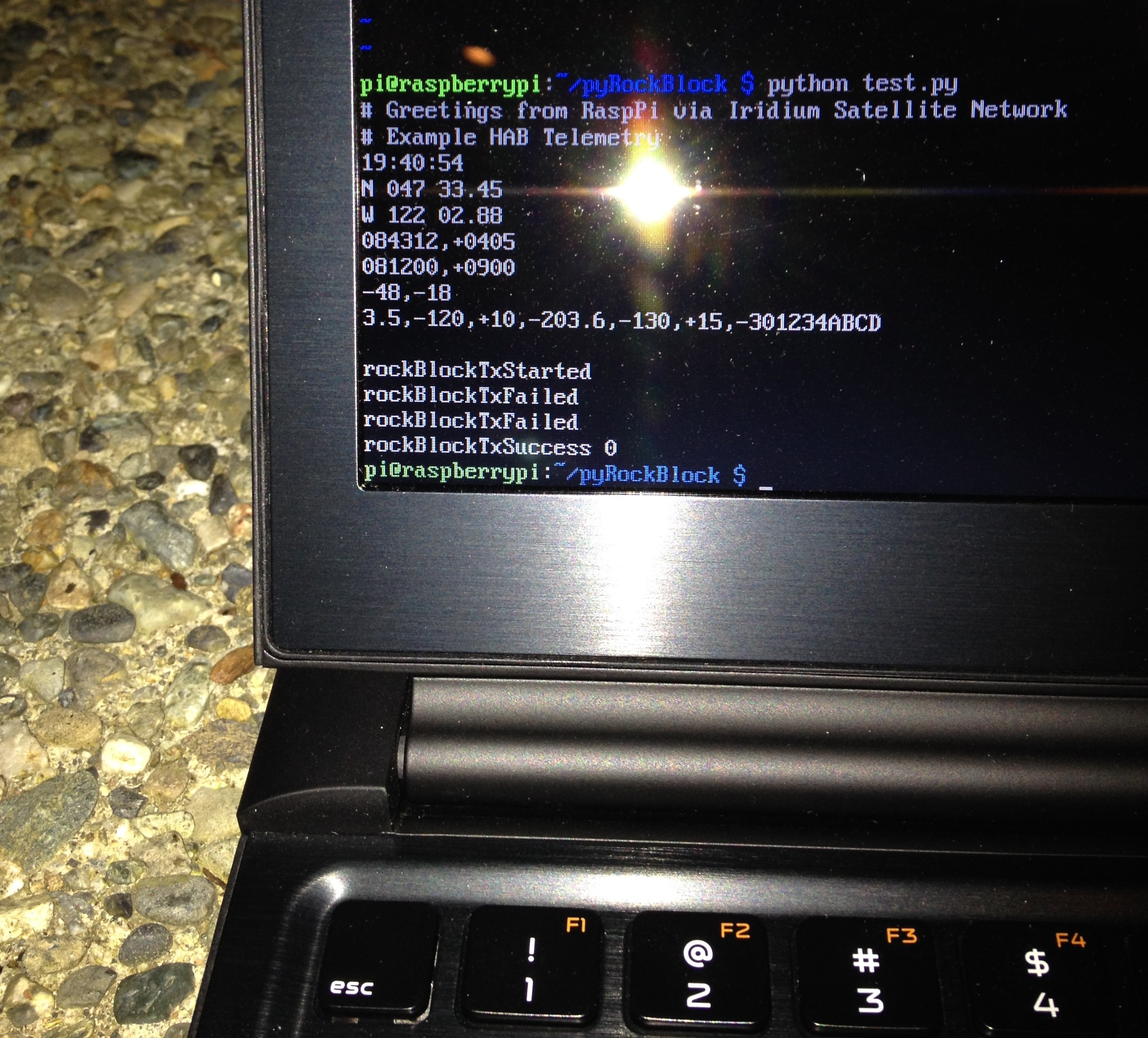
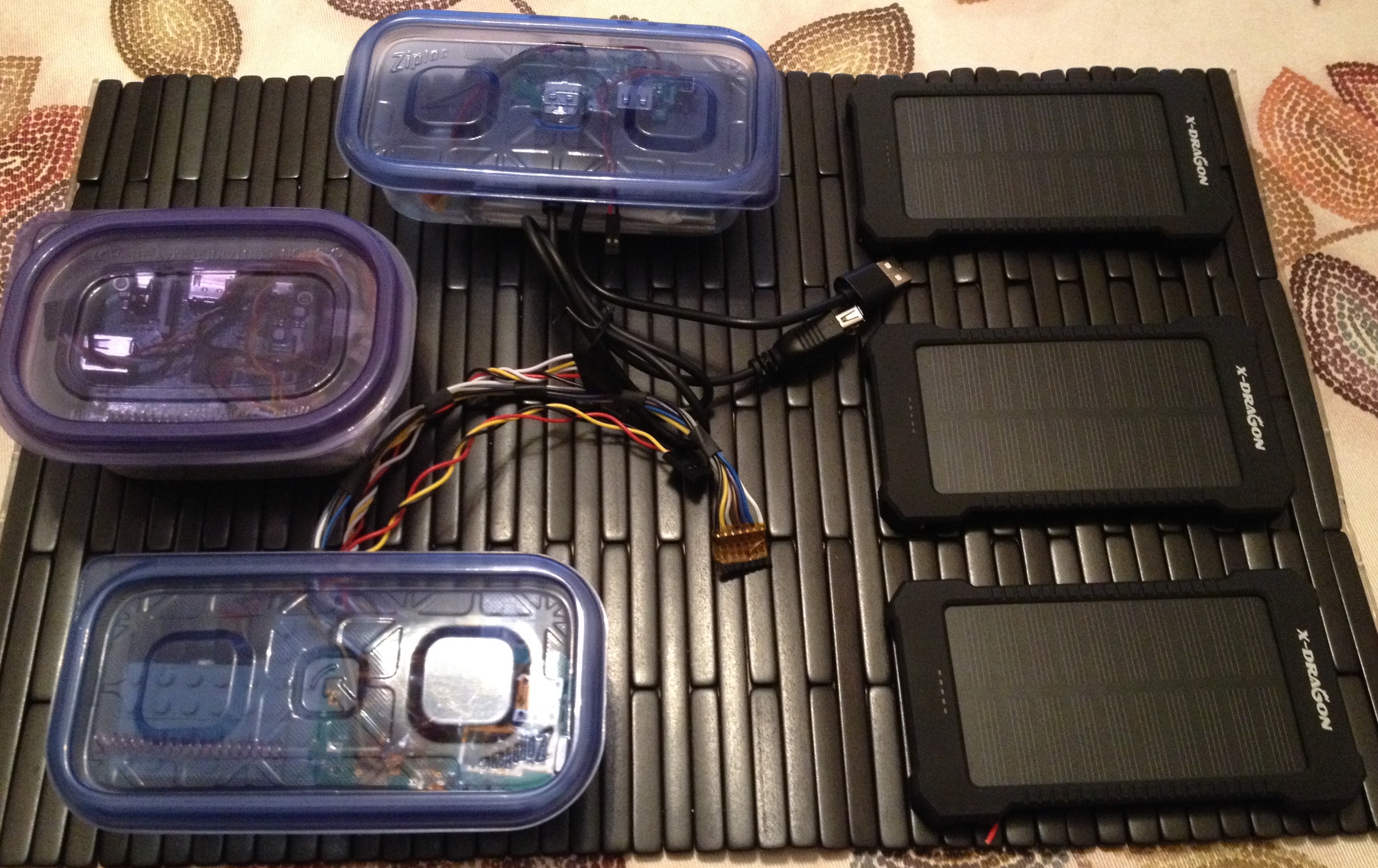
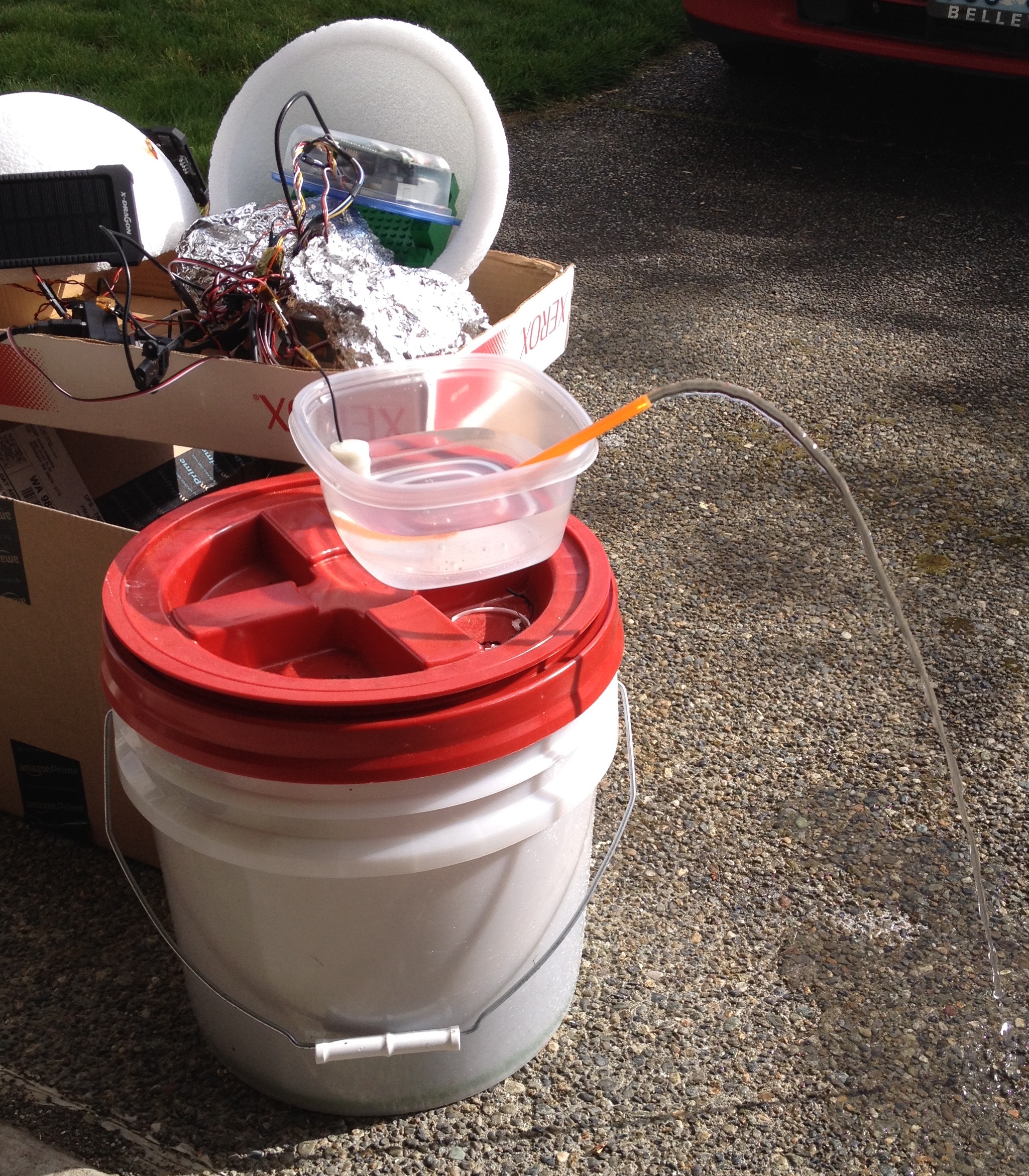
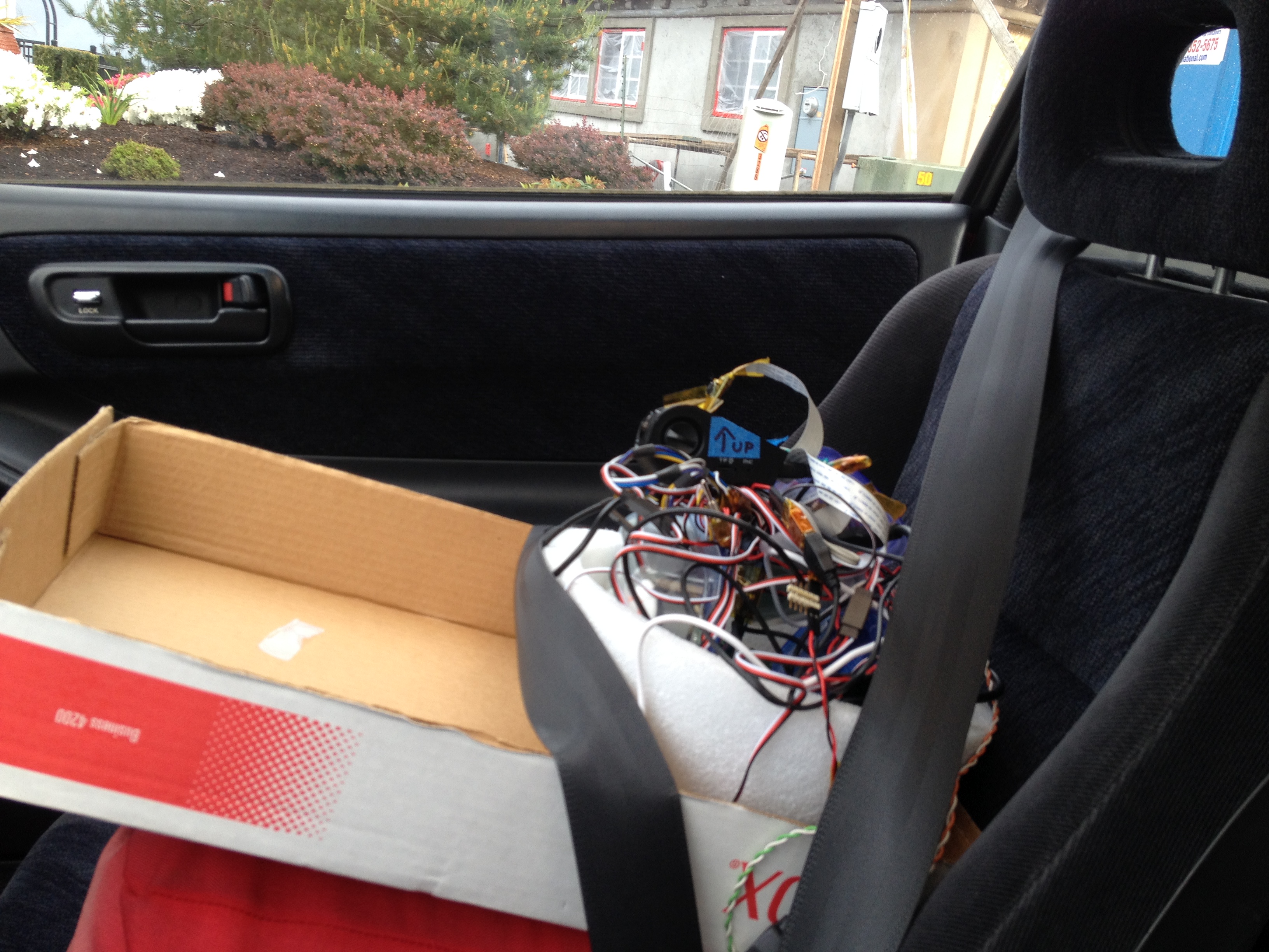
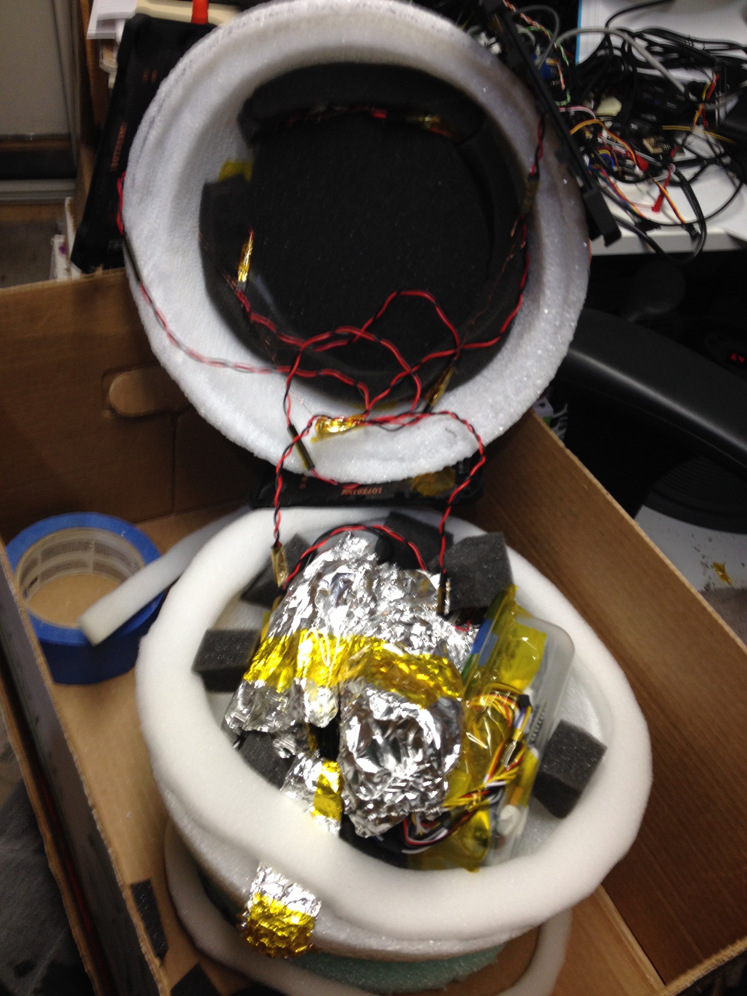
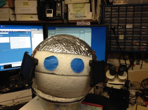


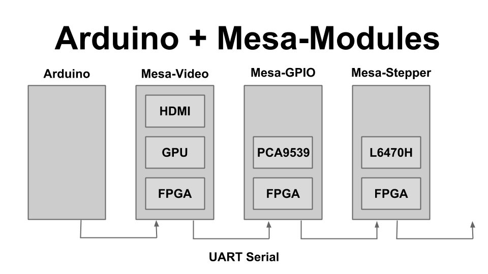


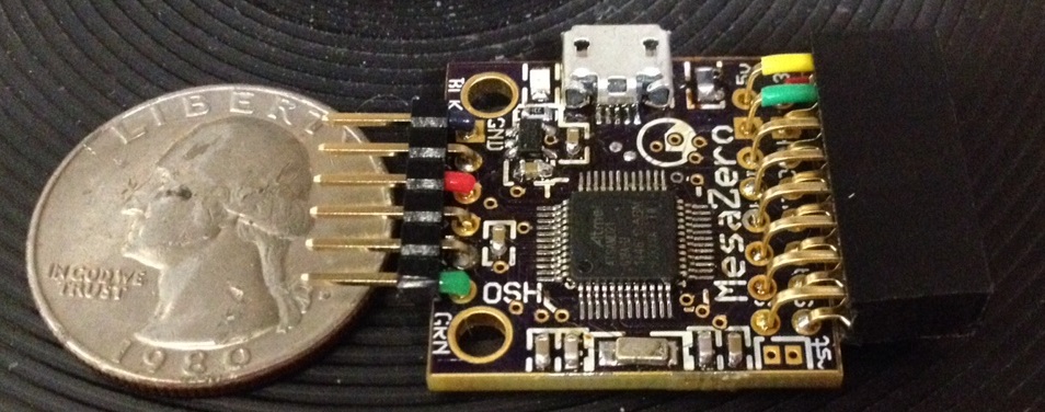


![clip_image002[20]](https://blackmesalabs.files.wordpress.com/2015/08/clip_image00220.jpg)


