2018.03.14 : WARNING : The 100pF cap was originally placed incorrectly on the PCB layout. It was connected to GND when it should be connected to Vout. Gerbers have now been corrected and a new Shared Project uploaded to OSH-Park. Also, at the end of this post is an alternative design using a different controller and inductor. It has a 3A capacity and a much wider input and output voltage range. It is untested as of this writing.
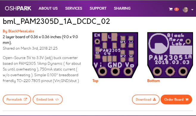
2018.03.03 : This post is an open source hardware design from Black Mesa Labs for a simple DC/DC converter for dropping 5V to 3.3V ( or adjustable to lower voltages via resistor selections ). The design is based on the PAM2305 from Diodes Incorporated, a great little 1 Amp step-down DC-DC converter in a small TSOT25 package. The PAM2305 supports a range of input voltages from 2.5V to 5.5V, allowing the use of a single Li+/Li-polymer cell, multiple Alkaline/NiMH cell, USB, and other standard power sources. The output voltage is adjustable from 0.6V to the input voltage.
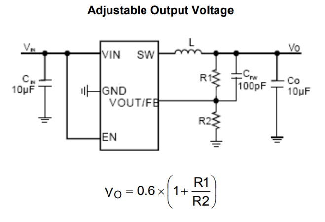
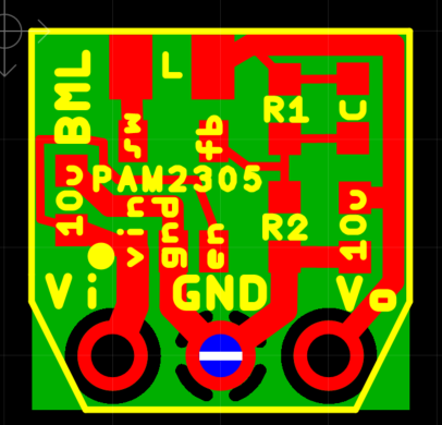
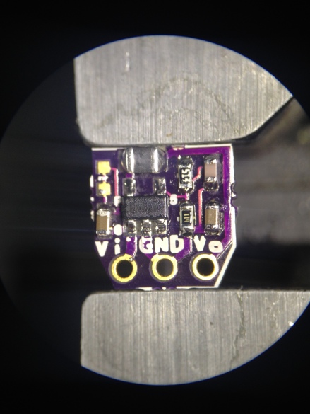
Black Mesa Labs has designed this simple 2-layer 9x9mm PCB of the above circuit in a 7805 TO-220 compatible pinout ( 3 pin 0.100″ Vin, Ground, Vout ) which is breadboard friendly.
The bare PCBs may be ordered from OSH-Park for only $0.60 for Qty-3 from this link.
The Bill of Materials is very small. All parts available from Digikey for less than $2. Note, if you don’t already have a resistor kit, I highly recommend this one, $23 for 170 1% values in 0603. Note: The inductors chosen were not ideal, The PAM2305 datasheet recommends an inductor current rating of 400mA above maximum output current. This 2.2uH at 1.8 Amp rating looks promising for next iteration for 1.0V builds. This 3.3 uH at 1.2Amp rating might be better for 3.3V builds.
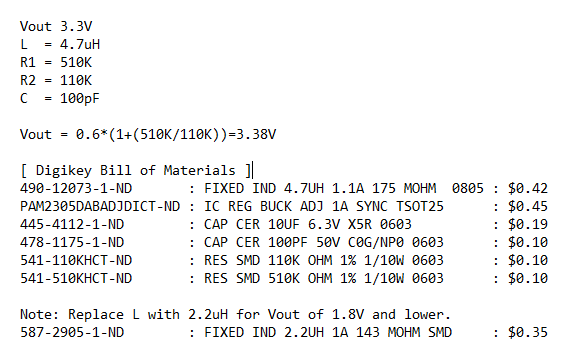
For resistor selection, an on-line calculator like this one for the LM317 can be helpful. The PAM2305 has a 600mV reference voltage however ( vs 1.25V for the LM317 ) so the desired voltage out needs to be scaled up 2.08x – also R1 and R2 are reversed. For example, for 1.00V desired output voltage, plug in 2.08V into the online calculator. Going through some standard 1% resistor values results in R1=150K, R2=100K. These then need to be swapped around for the PAM2305 so that R1=100K, R2=150K. Vout = 0.6*(1+(100K/150K)) = 1.00 Volts. Alternatively, BML created a Google Doc spreadsheet here for PAM2305 voltage out calculation given R1 and R2 inputs.
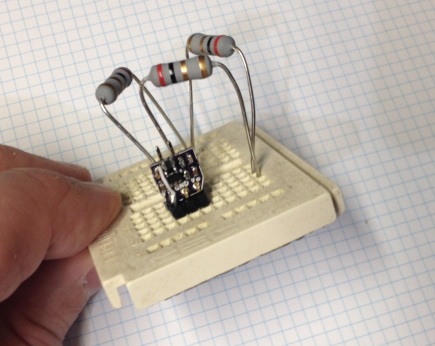
Circuit fully assembled.
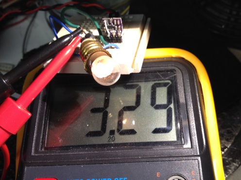
With a test load using a 3V inductive lamp. Vout is 3.29 volts at 100mA.
Power resistors were used for testing at maximum current. Test showed that running at 1A with a 3 ohm load (3W) the circuit was operational for about 5 seconds before overheating and dropping the output voltage to around 2.5V. Reducing the load to 4 ohms ( 2.7W ) the circuit did not overheat and sustained 3.20 volts at the load. In the future Black Mesa Labs may do a different version of this board design utilizing the 6-WDFN Exposed Pad package as it can dissipate 1W versus the 400mW of the TSOT-25 package. Here is a handy on-line V=IR ohms law calculator where you can dial in a voltage and current to solve for load resistor to test with ( or just use a calculator ).
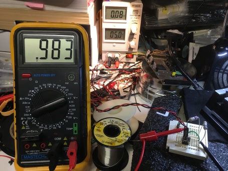
The 1.0V version of this project ( R1 = 100K, R2 = 150K ) was tested with 3ohm, 2ohm and 1ohm loads with the following results:
3ohm Load: Input 5V@80mA, 400mW. Output 983mV@328mA, 322mW. 80% Efficient
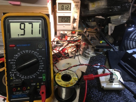
2ohm Load: Input 5V@120mA, 600mW. Output 971mV@486mA, 471mW. 79% Efficient
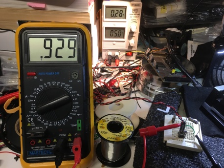
1ohm Load: Input 5V@280mA, 1,400mW. Output 929mV@929mA, 860mW. 61% Efficient. This experimented should be repeated using soldered connections – suspect the voltage drop may just be due to resistance in the breadboard.
Twitter video of this project:
[ Alternate Design ]
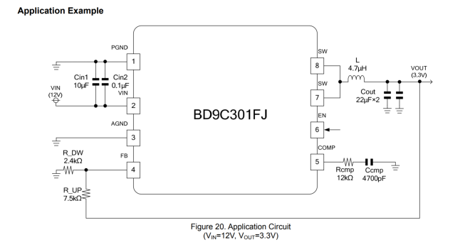
Available here from oshpark is an experimental alternate design using the 3A BD9C301FJ buck converter along with the SPM6530T4R7M inductor. All the components are bigger, cost more, but you get 5V-18V input range and 3Amps output. BML has not built this design yet, but is included here as an experiment.
The PCB has components on both sides. Top.
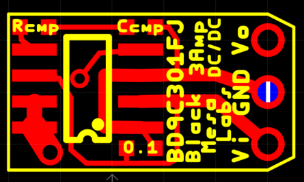
Bottom
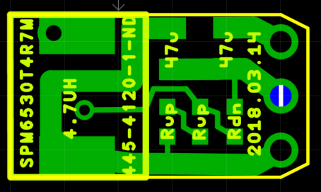
The capacitors are 0805s, all other passives are 0603s. Note that there are two Rup resistors in series. This is to allow precise Rup/Rdn voltage divider using a limited set of 1% resistors.
EOF

[…] open source small DC/DC 3W switcher to drop 5V to 3V in a 7805 TO-220 pinout from Black Mesa […]
LikeLike
[…] package and you’ve probably got our attention. Make that something both tiny and useful, like this 5-volt to 3.3-volt converter in a TO-220 sized package, and that’s something to get excited about. It’s a switch mode power supply that takes […]
LikeLike
[…] package and you’ve probably got our attention. Make that something both tiny and useful, like this 5-volt to 3.3-volt converter in a TO-220 sized package, and that’s something to get excited about. It’s a switch mode power supply that takes the same […]
LikeLike
[…] package and you’ve probably got our attention. Make that something both tiny and useful, like this 5-volt to 3.3-volt converter in a TO-220 sized package, and that’s something to get excited about. It’s a switch mode power supply that takes […]
LikeLike
[…] package and you’ve probably got our attention. Make that something both tiny and useful, like this 5-volt to 3.3-volt converter in a TO-220 sized package, and that’s something to get excited about. It’s a switch mode power supply that takes […]
LikeLike
[…] package and you’ve probably got our attention. Make that something both tiny and useful, like this 5-volt to 3.3-volt converter in a TO-220 sized package, and that’s something to get excited about. It’s a switch mode power supply that takes […]
LikeLike
[…] package and you’ve probably got our attention. Make that something both tiny and useful, like this 5-volt to 3.3-volt converter in a TO-220 sized package, and that’s something to get excited about. It’s a switch mode power supply that takes […]
LikeLike
[…] package and you’ve probably got our attention. Make that something both tiny and useful, like this 5-volt to 3.3-volt converter in a TO-220 sized package, and that’s something to get excited about. It’s a switch mode power supply that takes […]
LikeLike
[…] package and you’ve probably got our attention. Make that something both tiny and useful, like this 5-volt to 3.3-volt converter in a TO-220 sized package, and that’s something to get excited about. It’s a switch mode power supply that takes the same […]
LikeLike
[…] package and you’ve probably got our attention. Make that something both tiny and useful, like this 5-volt to 3.3-volt converter in a TO-220 sized package, and that’s something to get excited about. It’s a switch mode power supply that takes […]
LikeLike
[…] package and you’ve probably got our attention. Make that something both tiny and useful, like this 5-volt to 3.3-volt converter in a TO-220 sized package, and that’s something to get excited about. It’s a switch mode power supply that takes […]
LikeLike
There seems to be a discrepancy between the schematic and the PCB. In the schematic the 100 pF cap is between VOUT/FB and Vo, and on the PCB it’s between VOUT/FB and GND.
LikeLike
you are correct. I will fix that. Thank you.
LikeLike
[…] package and you’ve probably got our attention. Make that something both tiny and useful, like this 5-volt to 3.3-volt converter in a TO-220 sized package, and that’s something to get excited about. It’s a switch mode power supply that takes the same […]
LikeLike